Camera Control Unit GP-KS162CU
1.DC Power On/Off Switch (DC POWER, ON/OFF)
2.Auto White Balance Control Button (AWC SET)
The white balance can be set by pressing this button when the White Balance Selection Switch (4) is set to the AWC position.
3.White Balance Indicator
4.White Balance Selection Switch (WHITE BAL, AWC/ATW/MANU)
AWC : The white balance is automatically set and fixed by detecting the characteristic / color temperature of light source through the lens and controlling the gain of red and blue signal. The White Balance Indicator lights during the setting.
Note: When the White Balance Offset On/Off Switch is turned on, the fine adjustment for R/B gain is available by means of the R and B Gain Controls (5) after completing the white balance setting. The adjustable range is approx. 2,200K - 10,000K.
ATW : The white balance is automatically and contin- uously set by detecting the characteristic / color temperature of light source through the lens and controlling the gain of red and blue signal even if the characteristic / color temper- ature varies.
Note: When the White Balance Offset On/Off Switch is turned on, the fine adjustment for R/B gain is available by means of the R and B Gain Controls after completing the white balance setting. The adjustable range is approx. 2,300K - 6,000K.
MANU: The R/B gain of the white balance can be adjusted manually by means of the R and B Gain Controls.
The adjustable range of the white balance temperature is approx. 2,200K - 10,000K.
5.R / B Gain Controls (R/B)
These controls are used to adjust the R and B gain of the white balance.
6.Auto Light On/Off Switch (AUTO LIGHT ON/OFF) ON: When this switch is set to the ON position, the
video signal is set to the best level with the combi- nation of the Electronic light Control On/Off Switch(14) and AGC On/Off Switch(15).
7.Video Level Selection Switch (VIDEO LEVEL, MANU/OFF)
This switch is used to select the Video Level.
OFF: When this switch is set to the OFF position, the video signal is supplied with the standard level.
MANU: When this switch is set to the MANU position, the video level is adjustable by means of the Video Level Control (8).
Note:
This switch can be used as the Gain Up/Down Switch due to the value set by the Video Level Control (8).
8.Video Level Control (LEVEL)
This controls the video level when the Video Level Selection Switch (7) is set to the MANU position.
The video level control depends on the Auto Light On/Off Switch (6) setting as shown below.
AUTO LIGHT OFF :
By turning this counterclockwise, the video level is decreased.
By turning this clockwise, the video level is increased.
The video level setting at the center position of this control is higher than the standard one.
AUTO LIGHT ON :
By turning this counterclockwise, the standard video level is decreased.
By turning this clockwise, the standard video level is increased.
The standard video level setting at the center posi- tion of this control is higher than standard one.
9.Camera Cable Connector (CAMERA)
This
Caution: Connecting or disconnecting the camera cable must be done after turning OFF the Power ON/OFF Switch.
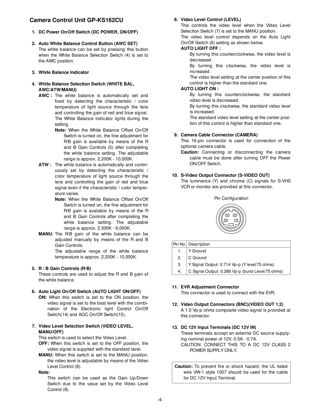
10.S-Video Output Connector (S-VIDEO OUT)
The luminance (Y) and chroma (C) signals for
Pin Configuration
4 | 3 |
2 | 1 |
Pin No. | Description |
|
|
1. | Y Ground |
2. | C Ground |
3. | Y Signal Output: 0.714 |
4. | C Signal Output: 0.286 |
|
|
11.EVR Adjustment Connector
This connector is used to connect with the EVR.
12.Video Output Connectors (BNC)(VIDEO OUT 1,2)
A 1.0
13.DC 12V Input Terminals (DC 12V IN)
These terminals accept an external DC source supply- ing nominal power of 12V, 0.5A - 0.7A.
CAUTION: CONNECT THIS TO A DC 12V CLASS 2 POWER SUPPLY ONLY.
Caution: To prevent fire or shock hazard, the UL listed wire