PCG-GR150/GR150K/GR170/GR170K
Service and Inspection Precautions
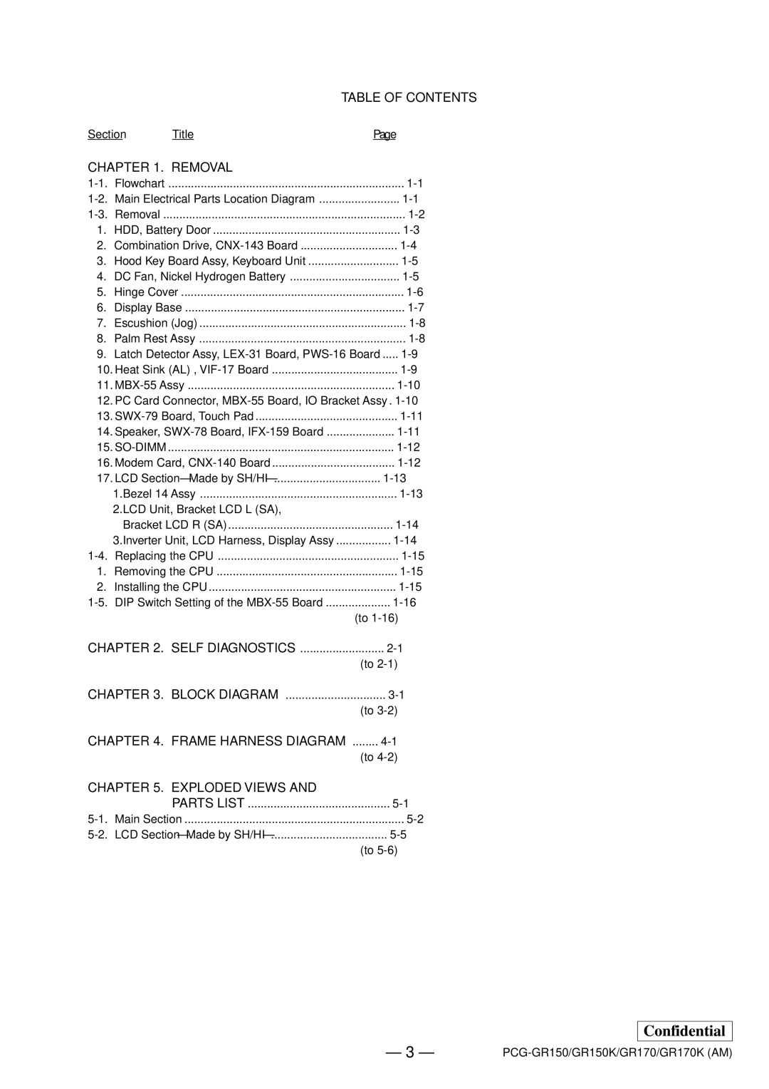
Table of Contents
Chapter Removal
Main Electrical Parts Location Diagram
Removal
HDD, Battery Door
Screw M1.7X3.5 X2 Black
Combination Drive, CNX-143 Board
Hood Key Board Assy, Keyboard Unit
DC Fan, Nickel Hydrogen Battery
Hinge Cover
Display Base
Palm Rest Assy
Escushion Jog
Heat Sink AL , VIF-17 Board
Latch Detector Assy, LEX-31 Board, PWS-16 Board
MBX-55 Assy
PC Card Connector, MBX-55 Board, IO Bracket Assy
Speaker, SWX-78 Board, IFX-159 Board
SWX-79 Board, Touch Pad
Modem Card, CNX-140 Board
SO-DIMM
Bezel 14 Assy
LCD Section Made by SH/HI
LCD Unit, Bracket LCD L SA, Bracket LCD R SA
Removing the CPU
Installing the CPU
DIP Switch Setting of the MBX-55 Board
Chapter Self Diagnostics
PCG-GR Series/PCGA-PRGR1
Chapter Frame Harness Diagram
Chapter Exploded Views and Parts List
Main Section
B3K
LCD Section Made by SH /HI
Vaio Notebook Quick Start
Vaio Notebook Quick Start
Contents
Troubleshooting the Modem
Welcome
Features
Remove the following hardware items from the box
Unpacking Your Notebook
Other
Recovery CDs
Documentation
Software CDs
Registering Your Notebook
Vaio Notebook Quick Start
Setting Up Your Vaio Notebook
Locating Controls and Ports
DVD-ROM drive S400 port † Multipurpose bay
Link IEEE1394
Right
Back
Bottom
Using the AC Adapter
Connecting a Power Source
To insert the battery pack
Using Battery Power
To charge the battery pack
Lift the battery bay cover up until it clicks into place
To view battery indicators
Battery Indicator Description
Battery Indicator Description Light Status
Push in and lift up the battery bay cover until it clicks
To remove the battery pack
Vaio Notebook Quick Start
Starting Your Notebook
Power button
Shutting Down Your Notebook
Hibernate Mode
Using Power Saving Modes
Normal Mode
Standby Mode
To activate Hibernate mode
Adding Memory
Precautions and Procedures
Slot 1 MB Slot 2 MB
Typical expansion memory configuration
Models with 128 MB Memory
Models with 256 MB Memory
Removing memory module
Removing a Memory Module
Tighten the screw on the memory bay cover
Installing a Memory Module
Viewing the amount of memory
About the Software on Your Notebook
Adobe Premiere LE On selected models
Overview of Software
CompuServe
Netscape Communicator
Quicken
Smart Connect Windows 2000 only
Using Your Recovery CDs
Using the Application Recovery CDs
To use the Application Recovery CDs
To repair software applications using Vaio Support Agent
Using the Driver Recovery CD
Using the System Recovery CDs
To use the Driver Recovery CDs
If your notebook does not start from the Recovery CD
To use the System Recovery CDs
Vaio Notebook Quick Start
Troubleshooting
Troubleshooting the Notebook
My notebook starts but a Bios error appears
My notebook does not start
Troubleshooting the Notebook
My notebook stops responding or does not shut down
Sound of my notebook’s fan is too loud
Power management setting is not responding
My LCD screen is blank
Troubleshooting the LCD Screen
Want to change the video resolution of my display
Cannot switch the LCD display to TV, and vice versa
Troubleshooting the Mouse and Touchpad
My mouse does not work
My touchpad does not work properly
Pointer does not move while using the Touchpad or Mouse
Troubleshooting Drives, PC Cards, and Peripheral Devices
My floppy disk drive optional cannot write to a floppy disk
My optical disc drive is not playing my CD or DVD properly
My PC Card is not working
My optical disc drive tray does not open
Troubleshooting Software
My software program stops responding or crashes
Cannot use the DVgate software
Troubleshooting the Modem
My modem does not work
My modem connection is slow
Troubleshooting Audio
My speakers make no sound
My microphone does not work
Cannot print
Troubleshooting the Printer
Getting Help
Support Options
Vaio Support Agent
Using the Quick Fix Wizard
Vaio Notebook Quick Start
Common Solutions dialog box 1st level
Using Common Solutions
About Automatic Updates
Update Notification
Vaio Support Agent Properties
Using Support Central
Support Central Registration
Support Central Current Issues
Support Central Support Wizard
Index
Vaio Notebook Quick Start
Page
655-646-11
List of PCG-GR Series As of July