Manuals
/
Panasonic
/
Computer Equipment
/
All in One Printer
Panasonic
KX-FT21RS
manual
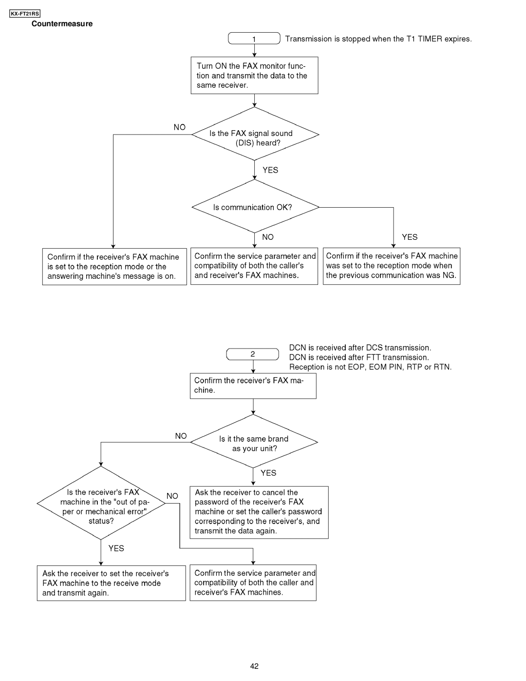
Countermeasure
Models:
KX-FT21RS
1
42
166
166
Download
166 pages
59.54 Kb
39
40
41
42
43
44
45
46
Troubleshooting
Specification
Install
Ccitt No Test Chart
User Recoverable Errors
Transmit problem
Reset Circuit
Disassembly Instructions
Battery Caution
Adjustments
Page 42
Image 42
KX-FT21RS
Countermeasure
42
Page 41
Page 43
Page 42
Image 42
Page 41
Page 43
Contents
KX-FT21RS
Contents
Battery Caution
Safety Precautions
For Service Technicians
Insulation Resistance Test
AC Caution
Personal Safety Precautions
Moving Sections of the Unit
Live Electrical Sections
Facsimile
Features
General
Integrated telephone system
Specifications
Optional Accessories
Ccitt No Test Chart
Location of Controls
Overview
Control Panel
Connections
Installation
Installing the Recording Paper
Document Stacker
Example Bill
Setting Your Logo
# , then
Press START/COPY/SET
To select characters with the dial keypad
Documents you can send
Maintenance Items and Component Locations
Maintenance Check ITEMS/COMPONENT Locations
Outline
Maintenance List Maintenance Cycle
Clean the document feeder rollers, sub roller
Maintenance Cleaning the Document Feeder Unit
Disconnect the power cord and the telephone
Line cord
Cleaning the Thermal Head
Cleaning the Pick UP Roller
Refer to 4 Disassembly Instruction
Troubleshooting Summary
Troubleshooting
Precautions
User Recoverable Errors
Document Jam
Troubleshooting Details
Starting Troubleshooting
Simple Check List
Troubleshooting Items Table
ADF Auto Document Feed Section
No document feed
Paper JAM
Multiple feed
Skew
Image is distorted When printing
Black or white vertical lines appear Skewed receiving image
KX-FT21RS
KX-FT21RS
Communication Section
Facsimile section
Transmit problem
Defective facsimile section
Sometimes there is a transmit problem
Reception problem
Check Document Paper JAM
Unit can copy, but cannot transmit/receive
Erroneous detection due to an echo or echo canceler
Echo/Echo Canceler
Cause and Countermeasure
Cause B
Causes and Countermeasures Cause a
Countermeasure a
Countermeasure B
Transmission Operation
Reception Operation
How to output the Journal Report
TX=TRANSMISSION RX=RECEPTION
Countermeasure
KX-FT21RS
KX-FT21RS
KX-FT21RS
KX-FT21RS
KX-FT21RS
KX-FT21RS
KX-FT21RS
Remote programming
Hint
KX-FT21RS
Program Mode Table
YES/NO
996 Journal
Please refer to the 2.3.4.3.1. Digital Block Diagram
Digital Board Section
Digital Block Diagram
KX-FT21RS
Normal Wave Patterns
Pin No. Diagram
KX-FT21RS
KX-FT21RS
NG Example
Check the Status of the Digital Board
Analog Board Section
Defective ITS Integrated Telephone System Section
Power Supply Board Section
Key components for troubleshooting
Troubleshooting Flow Chart
KX-FT21RS
Broken parts repair details D101, D102, D103, D104
Operation Board Section
No key operation No LCD indication
Sensor Section
Check the document sensor PS1
Check the read position PS2
Read Section
Refer to 6.4.4. Scanning Block
KX-FT21RS
Thermal Head Section
Refer to 6.4.3. Thermal Head
Programming and Lists
Operation
Operation Flow
Above values are the default values
Service Function Table
3ALL
Service Mode Settings Example of a printed out list
See 2.6.1. Printout Example
Other
Test Functions
Dtmf Signal Tone Transmit Selection
Button Code Table
Print Test Pattern
Mslt means Minimum Scan Line Time. Used only at the factory
Descriptions
Compression Code MH/MR
EQM
Printout Example
Adjustments
Adjusting the Feed Pressure
Disassembly Instructions
KX-FT21RS
KX-FT21RS
KX-FT21RS
KX-FT21RS
KX-FT21RS
KX-FT21RS
KX-FT21RS
KX-FT21RS
KX-FT21RS
KX-FT21RS
Flat Package IC Removal Procedure
Preparation
KX-FT21RS
Connection Diagram
General Block Diagram
Codec IC5 D/A converter
AC220V
+24V +5V
256k
Block Diagram
Control Section
100
Execute modulation and demodulation for the FAX
Asic IC1
Decodes the address
Transmits the recorded data to the thermal head
102
103
104
Vddc
Reset Circuit
ROM IC2
RAM IC3
Sram and RTC Back UP Circuit
Function
Circuit Operation
Supervision Circuit for the Thermal Head Temperature
LED Arraycis
Copy Fine, Super-Fine, Half Tone
Facsimile Section
Image Data Flow During Facsimile Operation
Transmission
Front/End
Block Diagram
Analog
Head 110
Thermal Head
112
Scanning Block
Stepping Motor Phase Pattern
Stepping Motor Drive Circuit
Mode Selection
Gear Section
Receive mode
Mode Operation
Transmit mode
Copy mode
See 6.5. Sensers and Switches
Scanning Printing
117
Copying
118
Sensors and Switches
All of the sensor and switches are shown below
119
Motor Position Sensor
Recording Paper Sensor SW201
120
Read Position Sensor PS2
Document Sensor PS1
121
On ITU-T International Telecommunications´ Union
Modem Section
Function
Definition of Each Group
Image transmission time
Concerning Transmission Time
Control time
Hold time
124
DIS/DTC DCS
125
126
CFR
Redundancy Compression Process Coding Mode
This unit uses one-dimensional MH format 127
Modem Circuit Operation
Analog Unit
Line Relay RLY1
NCU Section
General
Bell Detection Circuit
Line Amplifier and Side Tone Circuits
Monitor Circuit
Handset Circuit
EXT. TEL
Diagram
Circuit
KEY Scan
Analog Switch IC1 Control
Operation Panel
Key Matrix
Sensor Detection
LCD Control
Input Circuit
Power Supply Board Section
This power supply board uses the switching regulator method
Rectifier Circuit
KX-FT21RS
Over Current Limiter O.C.L
Surge Absorber Circuit
Control Circuit and Detecting Circuit
Over Voltage Circuit
For the Schematic Diagrams
Printed Circuit Board
141
TP8 TP7 C26
142
C230 C231 C106
D104 D103
SW201
C225
R215
L203
IC101
Q203
F101
145
Printed Circuit Board Operation Board
146
Schematic Diagram
147
Schematic Diagram Analog Circuit
148
Schematic Diagram Switching Power Supply
149
Schematic Diagram Operation Circuit
150
151
152
Operation Panel Section
153
Upper Cabinet Section
154
Lower CABINET/P.C.B. Section
155
Motor Section
Actual Size of Screws and Washer
157
158
This replacement parts list is for KX-FT21RS only
Cabinet and Electrical Parts
159
Digital Board Parts
160
161
Analog Board Parts
162
163
Operation Board Parts
164
Power Supply Board Parts
165
Fixtures and Tools
Top
Page
Image
Contents