KX-FT21RS
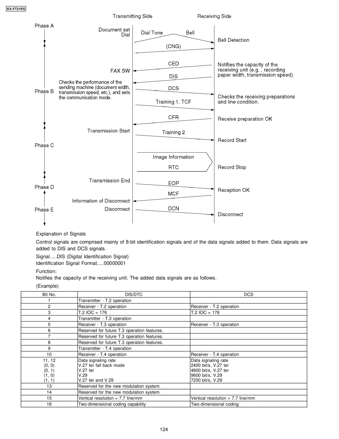
Explanation of Signals
Control signals are comprised mainly of
Signal.....DIS (Digital Identification Signal)
Identification Signal Format.....00000001
Function:
Notifies the capacity of the receiving unit. The added data signals are as follows. (Example)
Bit No. | DIS/DTC | DCS | |
1 |
| Transmitter - T.2 operation |
|
2 |
| Receiver - T.2 operation | Receiver - T.2 operation |
3 |
| T.2 IOC = 176 | T.2 IOC = 176 |
4 |
| Transmitter - T.3 operation |
|
5 |
| Receiver - T.3 operation | Receiver - T.3 operation |
6 |
| Reserved for future T.3 operation features. |
|
7 |
| Reserved for future T.3 operation features. |
|
8 |
| Reserved for future T.3 operation features. |
|
9 |
| Transmitter - T.4 operation |
|
10 | Receiver - T.4 operation | Receiver - T.4 operation | |
11, | 12 | Data signaling rate | Data signaling rate |
(0, | 0) | V.27 ter fall back mode | 2400 bit/s, V.27 ter |
(0, | 1) | V.27 ter | 4800 bit/s, V.27 ter |
(1, | 0) | V.29 | 9600 bit/s, V.29 |
(1, | 1) | V.27 ter and V.29 | 7200 bit/s, V.29 |
13 | Reserved for the new modulation system. |
| |
14 | Reserved for the new modulation system. |
| |
15 | Vertical resolution = 7.7 line/mm | Vertical resolution = 7.7 line/mm | |
16 | |||