Manuals
/
Panasonic
/
Kitchen Appliance
/
Microwave Oven
Panasonic
NN-L530BF, NN-S560BF, NN-S560WF
service manual
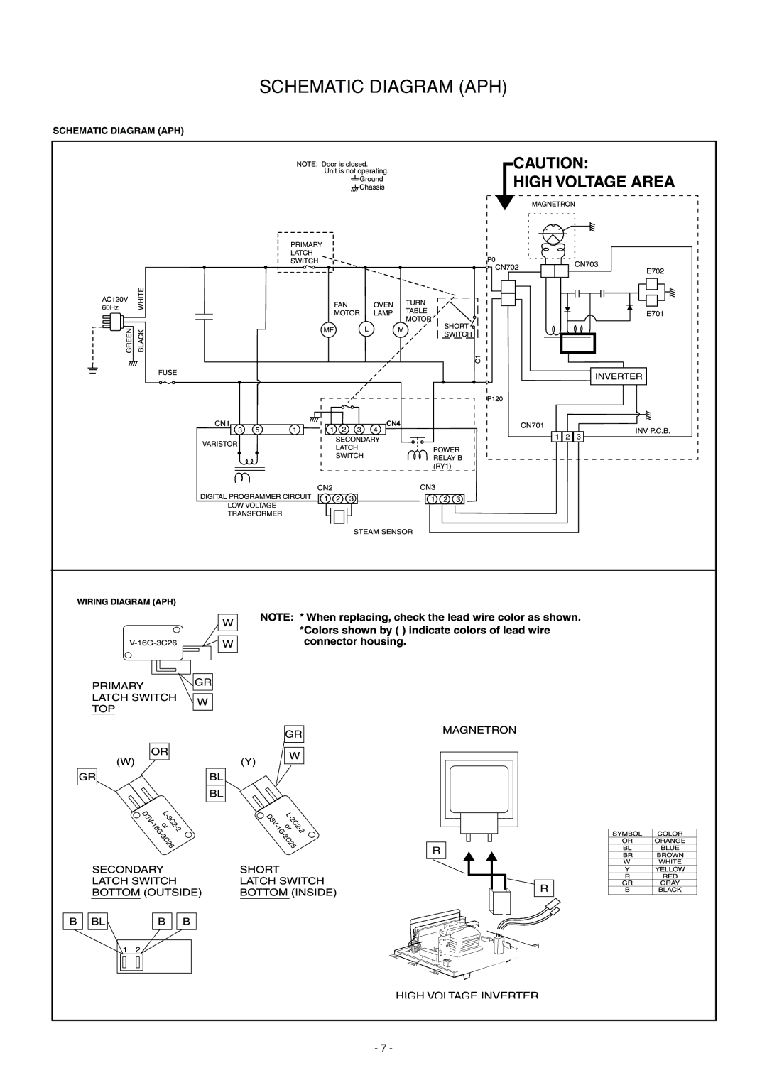
Schematic Diagram APH
Models:
NN-L530BF
NN-S560WF
NN-S560BF
1
8
36
36
Download
36 pages
25.15 Kb
5
6
7
8
9
10
11
12
Troubleshooting
Parts list
Feature Chart
Wiring Material
Stop/Reset Pad
Door assembly
Measurements and Adjustments
Variable power cooking control
Short Switch & Monitor
Page 8
Image 8
SCHEMATIC DIAGRAM (APH)
SCHEMATIC DIAGRAM (APH)
- 7 -
Page 7
Page 9
Page 8
Image 8
Page 7
Page 9
Contents
Microwave Oven
RPH Model refer to the last
Contents
Inverter Warning
Feature Chart
Control Panel
Stop/Reset Pad
Operation and Digital Programmer Circuit Test Procedure
Operation Scroll Display
Child
Schematic Diagram APH
Schematic Diagram CPH
Variable power cooking control
Inverter Power Supply Circuit NEW H,V
Variable Power Cooking
Description of Operating Sequence
Sensor Reheat NN-S560BFAPH/CPH,NN-S560WF APH/CPH
Sensor Cooking NN-S560BFAPH/CPH NN
Explanation of the Auto Sensor Cooking process
Check the grounding
Inverter Warnings NEW H.V
Confirm after repair
Microwave Radiation
Disassembly and Parts Replacement Procedure
Steam Sensor
Door assembly
Until alignment is achieved
Inverter Power Supply U
Primary Latch Switch, Secondary Secondary Latch
Switch and Power Relay B Interlocks
Short Switch & Monitor
Membrane key board Membrane switch assembly
Steam Sensor and Digital Programmer Circuit
1min. test
Measurements and Adjustments
Measurement of microwave output
Record keeping and notification after measurement
Procedure for Measuring Microwave Energy Leakage
Procedure for measuring radiation leakage
Troubleshooting Guide
Symptom Cause Corrections
DPC
Troubleshooting of Inverter Circuit U and Magnetron NEW H.V
Trouble Related to Digital Programmer Circuit
Exploded View and Parts List
Parts List
Ref.No Part name & Description Pcs Remarks Set
FAN Motor
Door Assembly
4T0 Ref.No Part name & Description Pcs Remarks Set
Escutheon Base Assembly
Packing and Accesories
Wiring Material
Parts List
Digital Programmer Circuit
Digital Programmer Circuit
Page
Page
Model for Latin America & Mexico
Top
Page
Image
Contents