Setup for Input Signals
Component/RGB-in Select
Select the input signals to be connected by installing the Optional Terminal Board. (Refer to the service manual for the optional Terminal Board.)
Select to match the signals from the source connected to the Component/RGB input terminals.
Y, PB, PR signals ![]() “Component”
“Component”
R, G, B, HD, VD signals ![]() “RGB”
“RGB”
|
| INPUT |
| SURROUND |
|
|
| VOL |
N |
| R |
PICTURE | SOUND | SET UP |
PICTURE |
|
|
POS. /SIZE |
| ASPECT |
1
2
SET UP
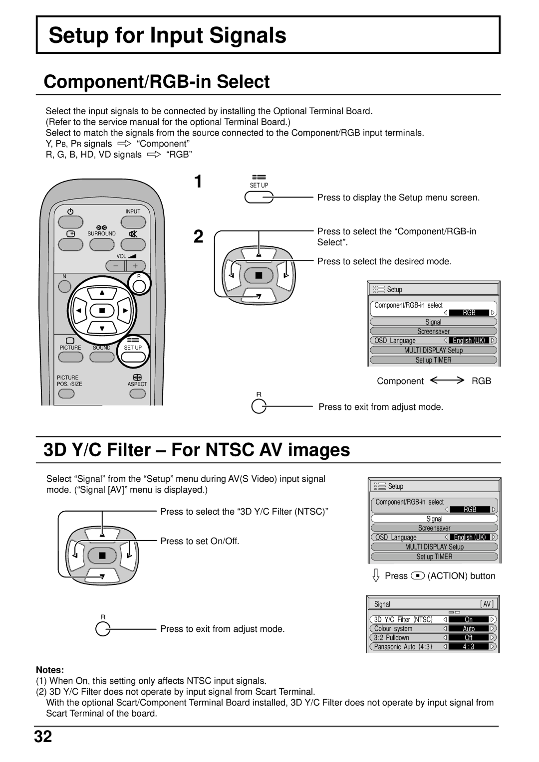
Press to display the Setup menu screen.
Press to select the
![]() Press to select the desired mode.
Press to select the desired mode.
Setup |
|
RGB | |
| |
Signal |
|
Screensaver | English (UK) |
OSD Language | |
MULTI DISPLAY Setup | |
Set up TIMER |
|
Component | RGB |
R
Press to exit from adjust mode.
3D Y/C Filter – For NTSC AV images
Select “Signal” from the “Setup” menu during AV(S Video) input signal mode. (“Signal [AV]” menu is displayed.)
Press to select the “3D Y/C Filter (NTSC)”
![]() Press to set On/Off.
Press to set On/Off.
Setup |
|
RGB | |
| |
Signal |
|
Screensaver | English (UK) |
OSD Language | |
MULTI DISPLAY Setup | |
Set up TIMER |
|
Press  (ACTION) button
| Signal | [ AV ] |
R | 3D Y/C Filter (NTSC) | On |
Press to exit from adjust mode. | Colour system | Auto |
| 3:2 Pulldown | Off |
| Panasonic Auto (4:3) | 4 : 3 |
Notes:
(1)When On, this setting only affects NTSC input signals.
(2)3D Y/C Filter does not operate by input signal from Scart Terminal.
With the optional Scart/Component Terminal Board installed, 3D Y/C Filter does not operate by input signal from Scart Terminal of the board.
32