Connections
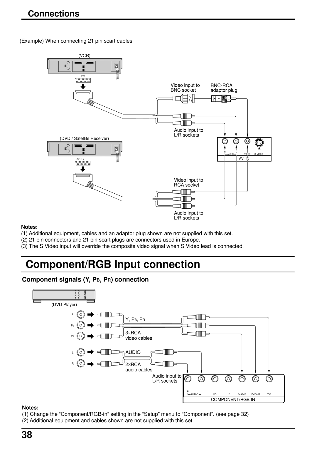
(Example) When connecting 21 pin scart cables
(VCR)
AV2
(DVD / Satellite Receiver)
AV1/TV
Video input to |
| |||||
BNC socket | adaptor plug | |||||
|
|
|
|
|
|
|
|
|
|
|
|
|
|
|
|
|
|
|
|
|
|
|
|
|
|
|
|
Audio input to
L/R sockets
R | L |
|
AUDIO | VIDEO | S VIDEO |
| AV IN |
|
Video input to
RCA socket
Audio input to
L/R sockets
Notes:
(1)Additional equipment, cables and an adaptor plug shown are not supplied with this set.
(2)21 pin connectors and 21 pin scart plugs are connectors used in Europe.
(3)The S Video input will override the composite video signal when S Video lead is connected.
Component/RGB Input connection
Component signals (Y, PB, PR) connection
(DVD Player)
Y
| Y, PB, PR | |
PB |
| |
PR | 3⋅ RCA | |
video cables | ||
| ||
L | AUDIO | |
R | 2⋅ RCA | |
| ||
| audio cables |
Audio input to
L/R sockets
R | L | HD |
|
| |||
|
| AUDIO |
| VD | PR/CR/R PB/CB/B | Y/G | |
|
|
| |||||
|
|
|
|
|
|
|
|
COMPONENT/RGB IN
Notes:
(1)Change the
(2)Additional equipment and cables shown are not supplied with this set.
38