English
Fitting procedure
4.Attaching the insulation spacers to the display unit
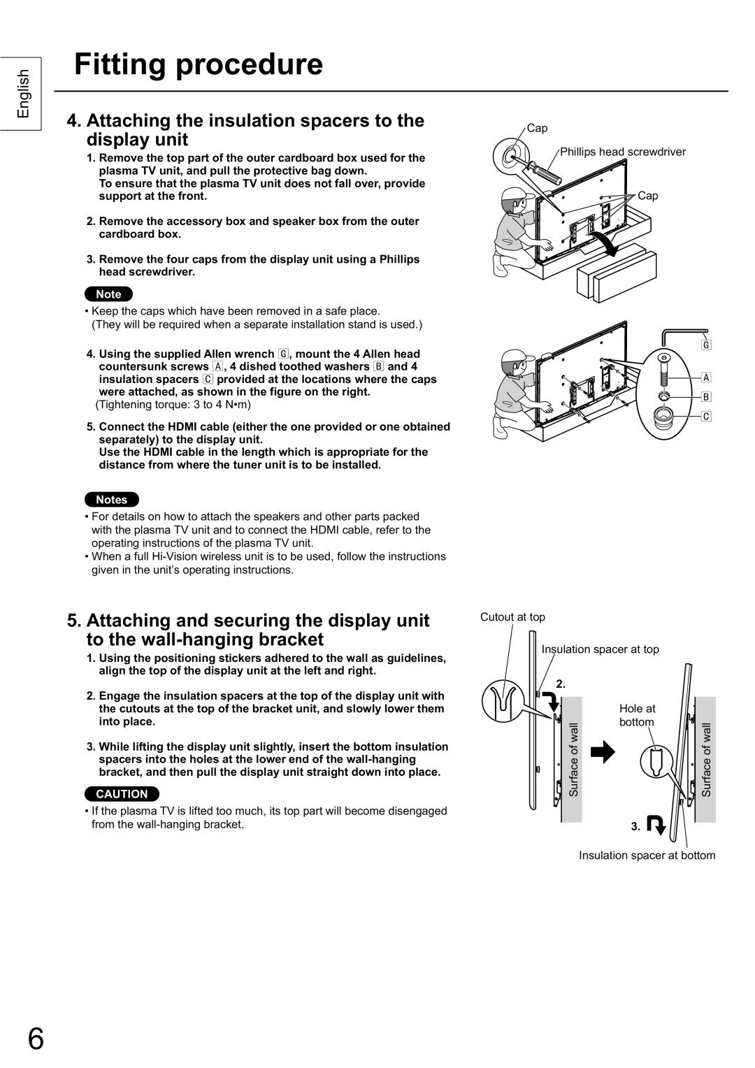
1.Remove the top part of the outer cardboard box used for the plasma TV unit, and pull the protective bag down.
To ensure that the plasma TV unit does not fall over, provide support at the front.
2.Remove the accessory box and speaker box from the outer cardboard box.
3.Remove the four caps from the display unit using a Phillips head screwdriver.
Note
•Keep the caps which have been removed in a safe place.
(They will be required when a separate installation stand is used.)
4. Using the supplied Allen wrench , mount the 4 Allen head
countersunk screws | , 4 dished toothed washers and 4 |
insulation spacers | provided at the locations where the caps |
were attached, as shown in the figure on the right. (Tightening torque: 3 to 4 N•m)
5.Connect the HDMI cable (either the one provided or one obtained separately) to the display unit.
Use the HDMI cable in the length which is appropriate for the distance from where the tuner unit is to be installed.
Notes
•For details on how to attach the speakers and other parts packed with the plasma TV unit and to connect the HDMI cable, refer to the operating instructions of the plasma TV unit.
•When a full
5.Attaching and securing the display unit to the
1.Using the positioning stickers adhered to the wall as guidelines, align the top of the display unit at the left and right.
2.Engage the insulation spacers at the top of the display unit with the cutouts at the top of the bracket unit, and slowly lower them into place.
3.While lifting the display unit slightly, insert the bottom insulation spacers into the holes at the lower end of the
CAUTION
•If the plasma TV is lifted too much, its top part will become disengaged from the
Cap
![]() Phillips head screwdriver
Phillips head screwdriver
Cap
Cutout at top
Insulation spacer at top |
| |
2. |
|
|
| Hole at |
|
Surface of wall | bottom | Surface of wall |
| ||
| 3. |
|
Insulation spacer at bottom
6
