WJ-FS409, WJ-FS316, WJ-FS416, WJ-FS309 specifications
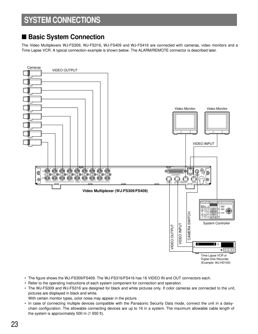
Panasonic's WJ-FS309, WJ-FS416, WJ-FS316, and WJ-FS409 are robust digital video multiplexers designed to enhance surveillance systems. These models incorporate advanced technologies and features critical for effective video management, making them suitable for various applications, including retail security, transportation, and public safety.The WJ-FS309 is known for its versatile functionality, allowing users to view and manage multiple camera feeds on a single display. It supports up to nine inputs, offering a compact solution for smaller installations. Its user-friendly interface simplifies operation, while features like real-time monitoring and on-screen display options enhance usability.
WJ-FS316 is an upgraded version, capable of accommodating 16 camera inputs. This model is equipped with a high-performance processor that ensures smooth video playback and rapid switching between feeds. It also features built-in motion detection, which alerts users to unusual activity, thereby increasing security effectiveness. Additionally, the WJ-FS316 supports a variety of output resolutions, providing flexibility for different display setups.
The WJ-FS409 stands out with its support for 4CIF resolution, ensuring high-quality video output essential for detailed surveillance. It also includes advanced video analysis capabilities, such as video motion detection and mask programming, which allow users to filter out unnecessary information, thus focusing on critical events. This feature is particularly useful in locations with high foot traffic, as it helps reduce the workload for security personnel.
The WJ-FS416 is a comprehensive solution that combines features from both the WJ-FS309 and WJ-FS409. It supports 16 channels and offers high-quality image processing, making it ideal for extensive surveillance systems. Its flexibility extends to network integration, allowing for seamless connectivity with existing security infrastructure. Users can remotely access camera feeds, creating a more dynamic monitoring experience.
Overall, these Panasonic models provide a robust and scalable approach to video surveillance. They incorporate essential technologies that streamline video management while ensuring high image quality and effective security monitoring. Through their thoughtful design and advanced features, the WJ-FS series underscores Panasonic's commitment to delivering reliable and innovative solutions for modern surveillance challenges.

