6. Synchronization Setting (SYNC)
You can select internal sync (INT) mode or
Whenever the VD2 signal is supplied to this camera, the camera automatically switches to the VD2 sync mode.
1.Move the cursor to SYNC and select LL or INT. The factory default setting is INT.
2.Press I.
If LL is selected, the SYNC menu appears. (If INT is selected, the synchronization mode is automatically set to internal sync pulse, and the menu is not displayed.)
Important Notices:
1.The priority for the sync modes is as follows:
1.Multiplexed vertical drive (VD2) (Highest priority)
2.
3.Composite color video or blackburst signal (VBS)
4.Composite B/W video or composite sync signal (VS)
5.Internal sync (INT) (Lowest priority)
2.When the internal sync mode is to be used, select INT. No
3.Whenever the multiplexed vertical drive pulse (VD2) is supplied to the camera from an external equipment such as a matrix switcher, the camera sync mode is automatically switched to the VD2 mode.
4.When the VBS or VS
5.The VBS
6.The VS
7.The
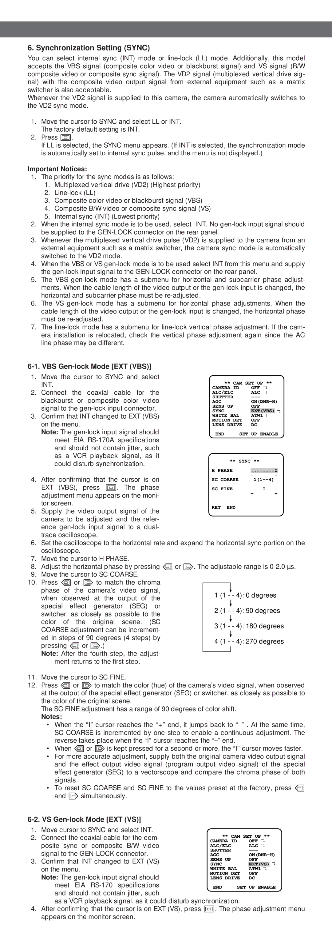
6-1. VBS Gen-lock Mode [EXT (VBS)]
1.Move the cursor to SYNC and select INT.
2.Connect the coaxial cable for the blackburst or composite color video signal to the
3.Confirm that INT changed to EXT (VBS) on the menu.
Note: The
** CAM SET UP ** |
| |||
CAMERA ID |
| OFF | ↵ |
|
ALC/ELC |
| ALC | ↵ |
|
SHUTTER |
|
|
| |
AGC |
| |||
SENS UP |
| OFF |
|
|
SYNC |
| EXT(VBS) | ↵ | |
WHITE BAL |
| ATW1↵ | ||
MOTION DET | OFF |
|
| |
LENS DRIVE | DC |
|
| |
END | SET | UP ENABLE | ||
** SYNC **
4. After confirming that the cursor is on EXT (VBS), press I. The phase adjustment menu appears on the moni- tor screen.
5. Supply the video output signal of the camera to be adjusted and the refer- ence
RET END
6. Set the oscilloscope to the horizontal rate and expand the horizontal sync portion on the oscilloscope.
7. Move the cursor to H PHASE.
8. Adjust the horizontal phase by pressing L or M. The adjustable range is
9. Move the cursor to SC COARSE.
10. Press L or M to match the chroma
phase of the camera’s video signal, when observed at the output of the
special effect generator (SEG) or switcher, as closely as possible to the
color of the original scene. (SC COARSE adjustment can be increment-
ed in steps of 90 degrees (4 steps) by pressing L or M.)
Note: After the fourth step, the adjust- ment returns to the first step.
11.Move the cursor to SC FINE.
12.Press L or M to match the color (hue) of the camera’s video signal, when observed at the output of the special effect generator (SEG) or switcher, as closely as possible to the color of the original scene.
The SC FINE adjustment has a range of 90 degrees of color shift.
Notes:
•When the “I” cursor reaches the “+” end, it jumps back to
•When L or M is kept pressed for a second or more, the “I” cursor moves faster.
•For more accurate adjustment, supply both the original camera video output signal and the effect output video signal (program output video signal) of the special effect generator (SEG) to a vectorscope and compare the chroma phase of both signals.
•To reset SC COARSE and SC FINE to the values preset at the factory, press L and M simultaneously.
6-2. VS Gen-lock Mode [EXT (VS)]
1. | Move cursor to SYNC and select INT. |
|
|
|
|
|
2. | Connect the coaxial cable for the com- | ** CAM SET UP ** | ||||
| posite sync or composite B/W video | CAMERA ID |
| OFF | ↵ | |
| ALC/ELC |
| ALC | ↵ | ||
| signal to the | SHUTTER |
|
|
| |
| AGC |
| ||||
3. | Confirm that INT changed to EXT (VS) | SENS UP |
| OFF |
|
|
SYNC |
| EXT(VS) | ↵ | |||
| on the menu. | WHITE BAL |
| ATW1↵ |
| |
| Note: The | MOTION DET | OFF |
|
| |
| LENS DRIVE | DC |
|
| ||
| meet EIA | END | SET UP ENABLE | |||
| and should not contain jitter, such |
|
|
|
|
|
as a VCR playback signal, as it could disturb synchronization.
4.After confirming that the cursor is on EXT (VS), press I. The phase adjustment menu appears on the monitor screen.