!6Day/Night Input Terminal (DAY/NIGHT IN/GND)
This terminal is used for connecting the camera to an external day/night detecting sen- sor.
!7AC Inlet Socket
Plug the power cord (supplied as a standard accessory) into this socket and connect it to an AC outlet.
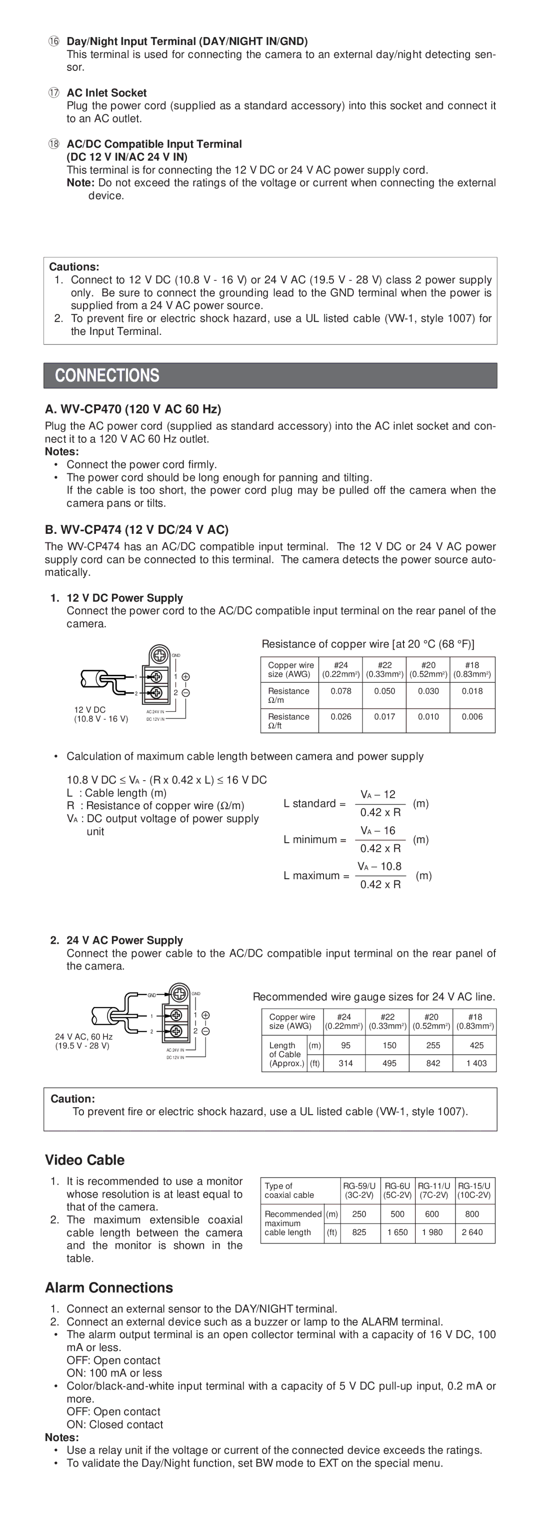
!8AC/DC Compatible Input Terminal (DC 12 V IN/AC 24 V IN)
This terminal is for connecting the 12 V DC or 24 V AC power supply cord.
Note: Do not exceed the ratings of the voltage or current when connecting the external device.
Cautions:
1.Connect to 12 V DC (10.8 V - 16 V) or 24 V AC (19.5 V - 28 V) class 2 power supply only. Be sure to connect the grounding lead to the GND terminal when the power is supplied from a 24 V AC power source.
2.To prevent fire or electric shock hazard, use a UL listed cable
CONNECTIONS
A. WV-CP470 (120 V AC 60 Hz)
Plug the AC power cord (supplied as standard accessory) into the AC inlet socket and con- nect it to a 120 V AC 60 Hz outlet.
Notes:
•Connect the power cord firmly.
•The power cord should be long enough for panning and tilting.
If the cable is too short, the power cord plug may be pulled off the camera when the camera pans or tilts.
B.WV-CP474 (12 V DC/24 V AC)
The
1.12 V DC Power Supply
Connect the power cord to the AC/DC compatible input terminal on the rear panel of the camera.
Resistance of copper wire [at 20 °C (68 °F)]
|
|
|
|
| GND |
|
|
|
|
|
|
|
| |
|
|
|
|
|
|
|
|
|
| Copper wire | #24 | #22 | #20 | #18 |
|
| 1 |
| 1 |
|
|
| size (AWG) | (0.22mm2) | (0.33mm2) | (0.52mm2) | (0.83mm2) | ||
|
|
|
|
| ||||||||||
|
|
|
|
|
|
|
|
|
|
|
|
|
|
|
|
|
|
|
|
|
|
|
|
| Resistance | 0.078 | 0.050 | 0.030 | 0.018 |
|
| 2 |
| 2 |
|
| ||||||||
12 V DC | AC 24V IN |
|
|
|
|
| Ω /m |
|
|
|
| |||
|
|
|
|
|
|
|
| |||||||
|
|
|
|
|
|
|
|
|
| |||||
|
|
|
|
| Resistance | 0.026 | 0.017 | 0.010 | 0.006 | |||||
(10.8 V - 16 V) | DC 12V IN |
|
|
|
|
| ||||||||
|
|
|
| |||||||||||
|
|
|
|
|
|
|
|
|
| Ω /ft |
|
|
|
|
• Calculation of maximum cable length between camera and power supply
10.8V DC ≤ VA - (R x 0.42 x L) ≤ 16 V DC
L : Cable length (m)
R : Resistance of copper wire (Ω /m)
VA : DC output voltage of power supply unit
L standard = | VA − | 12 |
| (m) |
|
|
| ||
|
| |||
| 0.42 x R | |||
L minimum = | VA − | 16 |
| (m) |
|
|
| ||
|
| |||
| 0.42 x R | |||
L maximum = | VA − | 10.8 |
| (m) |
|
|
| ||
|
|
| ||
0.42 x R
2.24 V AC Power Supply
Connect the power cable to the AC/DC compatible input terminal on the rear panel of the camera.
GND ![]()
![]() GND
GND
1 | 1 |
2 | 2 |
24 V AC, 60 Hz |
|
(19.5 V - 28 V) | AC 24V IN |
| |
| DC 12V IN |
Recommended wire gauge sizes for 24 V AC line.
Copper wire | #24 | #22 | #20 | #18 | |
size (AWG) | (0.22mm2) | (0.33mm2) | (0.52mm2) | (0.83mm2) | |
|
|
|
|
|
|
Length | (m) | 95 | 150 | 255 | 425 |
of Cable |
|
|
|
|
|
|
|
|
|
| |
(Approx.) | (ft) | 314 | 495 | 842 | 1 403 |
|
|
|
|
|
|
Caution:
To prevent fire or electric shock hazard, use a UL listed cable
Video Cable
1.It is recommended to use a monitor whose resolution is at least equal to that of the camera.
2.The maximum extensible coaxial cable length between the camera and the monitor is shown in the table.
Type of |
|
| |||
coaxial cable |
| ||||
|
|
|
|
|
|
Recommended | (m) | 250 | 500 | 600 | 800 |
maximum |
|
|
|
|
|
|
|
|
|
| |
cable length | (ft) | 825 | 1 650 | 1 980 | 2 640 |
|
|
|
|
|
|
Alarm Connections
1.Connect an external sensor to the DAY/NIGHT terminal.
2.Connect an external device such as a buzzer or lamp to the ALARM terminal.
•The alarm output terminal is an open collector terminal with a capacity of 16 V DC, 100 mA or less.
OFF: Open contact
ON: 100 mA or less
•
OFF: Open contact
ON: Closed contact
Notes:
•Use a relay unit if the voltage or current of the connected device exceeds the ratings.
•To validate the Day/Night function, set BW mode to EXT on the special menu.
