FEATURES
1.The following functions are built in.
(1)Auto Light Control (ALC)/Electronic Light Control (ELC)
(2)The
Dynamic range of 46 dB.
(3)Various External Sync Functions, including
(4)Auto/Manual White Balance Function
(5)Electronic Shutter Function
2.
3.Minimum Illumination of 0.8 lx (0.08
4.480 lines of horizontal resolution
5.High quality picture:
(a) 2H type vertical enhancer for greater picture sharpness
(b) Chroma averaging circuit for better color
(c) Minimum of aliasing on fine objects
(d) Expanded dynamic range by use of knee circuit
(e) Highlight aperture correction for greater picture detail of bright objects
6.Ability to shoot indoor scenes with fixed iris lens by use of Electronic Light Control (ELC) function.
7.Selectable electronic sensitivity enhancing modes including AUTO, MANUAL and OFF
8.
9.Auto
MAJOR OPERATING CONTROLS AND THEIR FUNCTIONS
q | we r | !2 !3 |
WV
| AC 120V 60Hz |
|
|
| VIDEO OUT | !4 | |
|
| POWER | |
|
| OUT | !5 |
| ALARM | GND |
|
|
|
| |
| DAY/ | GND | !6 |
| NIGHT | IN | |
t | !7 !2 !3 |
| |
!1 | i |
|
|
|
| |
|
|
|
|
| ||
|
|
| GND |
|
| |
|
| o |
| 1 | VIDEO OUT | |
|
|
| !8 |
|
| POWER |
|
| y | 2 |
|
| |
|
|
|
| ALARM | GND | |
|
|
|
|
| OUT | |
|
|
| AC 24V IN |
|
| |
|
|
|
| DAY/ | GND | |
|
|
| DC 12V IN |
| NIGHT IN | |
u!0
!4
!5
!6
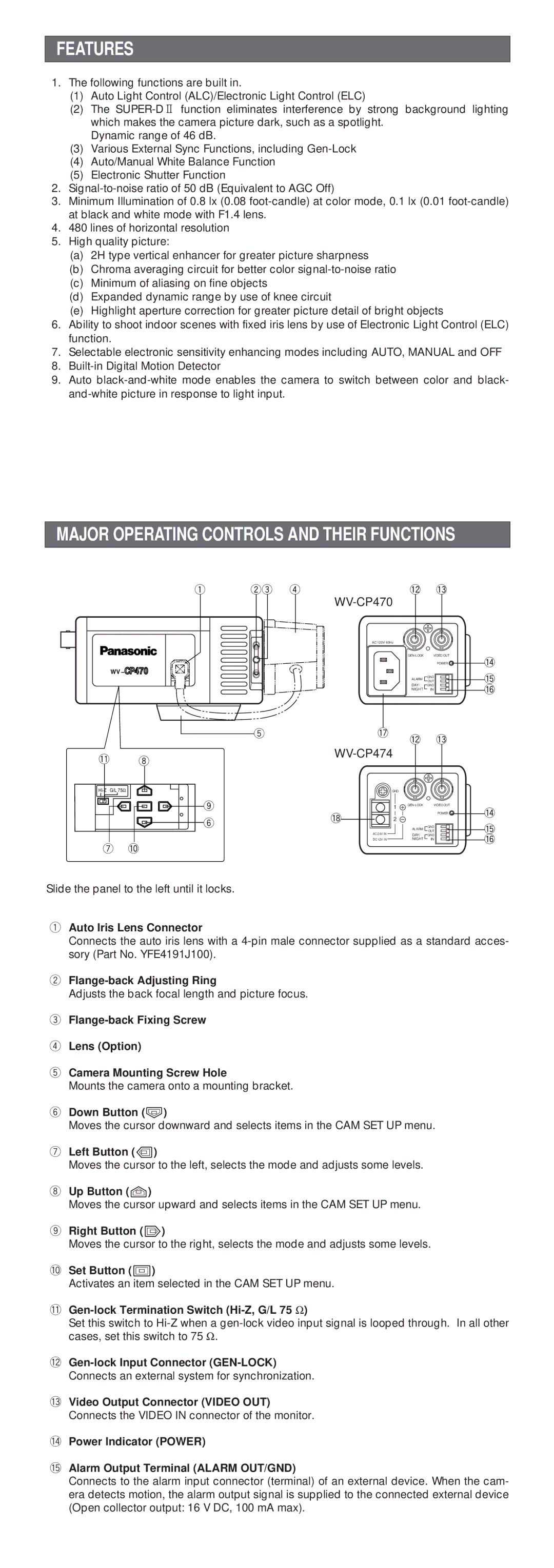
Slide the panel to the left until it locks.
qAuto Iris Lens Connector
Connects the auto iris lens with a
w
Adjusts the back focal length and picture focus.
e
rLens (Option)
tCamera Mounting Screw Hole
Mounts the camera onto a mounting bracket.
yDown Button (K)
Moves the cursor downward and selects items in the CAM SET UP menu.
uLeft Button (L)
Moves the cursor to the left, selects the mode and adjusts some levels.
iUp Button (J)
Moves the cursor upward and selects items in the CAM SET UP menu.
oRight Button (M)
Moves the cursor to the right, selects the mode and adjusts some levels.
!0Set Button (I)
Activates an item selected in the CAM SET UP menu.
!1Gen-lock Termination Switch (Hi-Z, G/L 75 Ω )
Set this switch to
Connects an external system for synchronization.
!3Video Output Connector (VIDEO OUT)
Connects the VIDEO IN connector of the monitor.
!4Power Indicator (POWER)
!5Alarm Output Terminal (ALARM OUT/GND)
Connects to the alarm input connector (terminal) of an external device. When the cam- era detects motion, the alarm output signal is supplied to the connected external device (Open collector output: 16 V DC, 100 mA max).