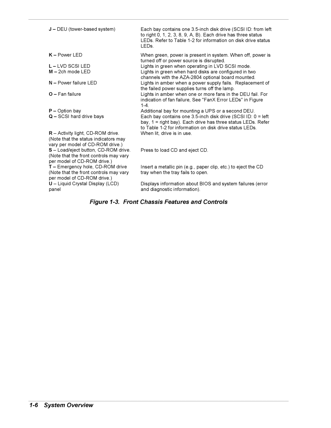
5800/180Ra-7 specifications
The NEC 5800/180Ra-7 is a high-performance server model that represents a significant advancement in the realm of enterprise computing. Launched by NEC, a renowned leader in information technology, this server is designed for critical business applications and is tailored to meet the demanding requirements of modern data centers.At the heart of the NEC 5800/180Ra-7 is its powerful computing architecture. It is equipped with a robust processor that offers multiple cores and threads, allowing for efficient multitasking and enhanced processing capabilities. This makes it suitable for heavy workloads, including database management, cloud computing, and virtualization services. The server's architecture ensures low latency and high throughput, enhancing the performance of applications running on it.
One of the standout features of the NEC 5800/180Ra-7 is its scalability. It supports a variety of configurations, enabling businesses to expand their resources as needed. This scalability is crucial for organizations that experience fluctuating demands or are in a growth phase, as it allows for easy upgrades without the need for a complete system overhaul.
In terms of memory and storage, the NEC 5800/180Ra-7 comes with a flexible architecture that supports large amounts of RAM and multiple storage options, including SSDs and HDDs. This flexibility ensures that businesses can tailor their server’s memory and storage capacities to fit specific applications and workloads, leading to better performance and faster data access times.
The server also includes advanced redundancy features to ensure high availability. With multiple power supplies, cooling systems, and RAID configurations, the NEC 5800/180Ra-7 minimizes downtime and ensures continuous operation, which is critical for mission-critical applications.
NEC has also integrated smart energy management technology into the 5800/180Ra-7. This technology helps reduce power consumption while maintaining optimal performance levels, making it a more environmentally friendly choice for data centers.
Furthermore, the server is built with security in mind. It includes various security features such as secure boot, TPM (Trusted Platform Module), and hardware-based encryption to protect sensitive data from unauthorized access and cyber threats.
In summary, the NEC 5800/180Ra-7 offers a combination of performance, scalability, energy efficiency, and security. With its advanced features and technologies, it serves as an ideal solution for enterprises looking to enhance their computing capabilities in today’s data-driven landscape. Its design caters to the evolving needs of businesses, making it a reliable choice for diverse applications across various industries.

