Major Operating Controls and Their Functions
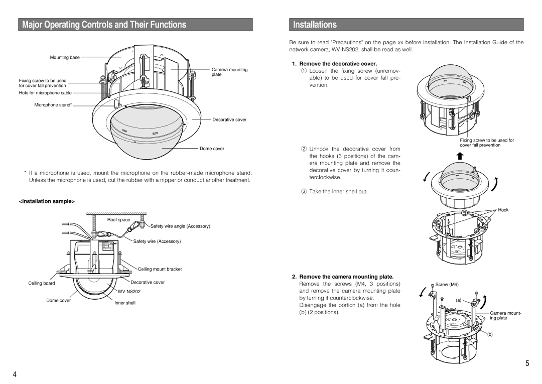
Mounting base
Camera mounting
plate
Fixing screw to be used for cover fall prevention
Hole for microphone cable
Microphone stand*
Decorative cover
Dome cover
*If a microphone is used, mount the microphone on the
<Installation sample>
Roof space
Safety wire angle (Accessory)
Installations
Be sure to read "Precautions" on the page xx before installation. The Installation Guide of the network camera,
1. Remove the decorative cover.
qLoosen the fixing screw (unremov-
able) to be used for cover fall pre- vention.
Fixing screw to be used for cover fall prevention
w Unhook the decorative cover from the hooks (3 positions) of the cam- era mounting plate and remove the decorative cover by turning it coun- terclockwise.
e Take the inner shell out.
Hook
T N O R F
Safety wire (Accessory)
Ceiling mount bracket |
T N O R F
Ceiling board
Dome cover
Decorative cover
Inner shell
2.Remove the camera mounting plate. Remove the screws (M4, 3 positions) and remove the camera mounting plate by turning it counterclockwise. Disengage the portion (a) from the hole
(b) (2 positions).
![]() Screw (M4)
Screw (M4)
(a)
Camera mount- ![]()
![]()
![]() ing plate
ing plate
T N O R F
(b)
T N O R F
5
4