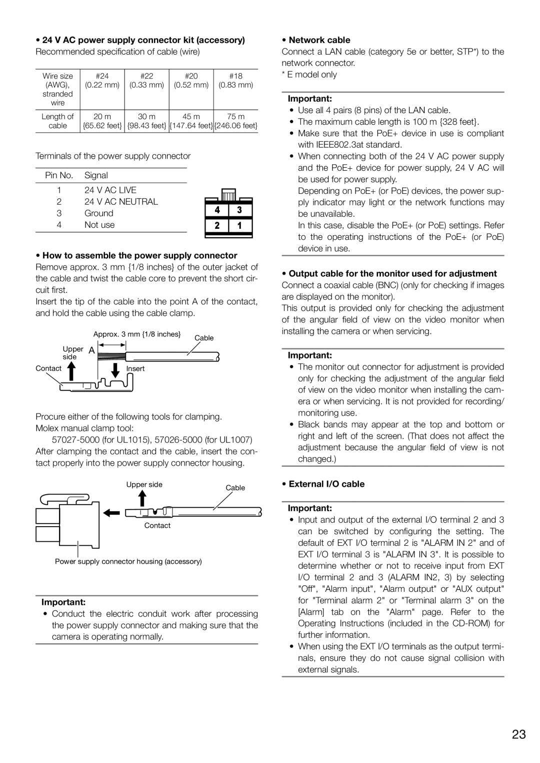
24 V AC power supply connector kit (accessory)

Recommended specification of cable (wire)

Wire size

#24

#22

#20


#18


(AWG),

(0.22 mm)

(0.33 mm)

(0.52 mm)


(0.83 mm)

stranded


wire


Length of

20 m

30 m

45 m


75 m

cable

{65.62 feet}

{98.43 feet}

{147.64 feet}

{246.06 feet}


Terminals of the power supply connector


Pin No.

Signal


1

24 V AC LIVE


2

24 V AC NEUTRAL


4


3


3

Ground


4

Not use


2


1


How to assemble the power supply connector

Remove approx. 3 mm {1/8 inches} of the outer jacket of the cable and twist the cable core to prevent the short cir- cuit first.

Insert the tip of the cable into the point A of the contact, and hold the cable using the cable clamp.


Approx. 3 mm {1/8 inches}

Cable


Upper

A


side


Contact


Insert


Procure either of the following tools for clamping. Molex manual clamp tool:

57027-5000 (for UL1015), 57026-5000 (for UL1007) After clamping the contact and the cable, insert the con- tact properly into the power supply connector housing.

Upper side

Cable


Contact

Power supply connector housing (accessory)

Important:

Conduct the electric conduit work after processing the power supply connector and making sure that the camera is operating normally.

• Network cable

Connect a LAN cable (category 5e or better, STP*) to the network connector.

*E model only

Important:

Use all 4 pairs (8 pins) of the LAN cable.

The maximum cable length is 100 m {328 feet}.

Make sure that the PoE+ device in use is compliant with IEEE802.3at standard.

When connecting both of the 24 V AC power supply and the PoE+ device for power supply, 24 V AC will be used for power supply.

Depending on PoE+ (or PoE) devices, the power sup- ply indicator may light or the network functions may be unavailable.

In this case, disable the PoE+ (or PoE) settings. Refer to the operating instructions of the PoE+ (or PoE) device in use.

Output cable for the monitor used for adjustment

Connect a coaxial cable (BNC) (only for checking if images are displayed on the monitor).

This output is provided only for checking the adjustment of the angular field of view on the video monitor when installing the camera or when servicing.

Important:

The monitor out connector for adjustment is provided only for checking the adjustment of the angular field of view on the video monitor when installing the cam- era or when servicing. It is not provided for recording/ monitoring use.

Black bands may appear at the top and bottom or right and left of the screen. (That does not affect the adjustment because the angular field of view is not changed.)

External I/O cable

Important:

Input and output of the external I/O terminal 2 and 3 can be switched by configuring the setting. The default of EXT I/O terminal 2 is "ALARM IN 2" and of EXT I/O terminal 3 is "ALARM IN 3". It is possible to determine whether or not to receive input from EXT I/O terminal 2 and 3 (ALARM IN2, 3) by selecting "Off", "Alarm input", "Alarm output" or "AUX output" for "Terminal alarm 2" or "Terminal alarm 3" on the [Alarm] tab on the "Alarm" page. Refer to the Operating Instructions (included in the CD-ROM) for further information.

When using the EXT I/O terminals as the output termi- nals, ensure they do not cause signal collision with external signals.

23

Page 23
Image 23
Panasonic WV-SW395E AC power supply connector kit accessory, How to assemble the power supply connector, Network cable

WV-SW395, WV-SW396E, WV-SW395E, WV-SW396 specifications

Panasonic's WV-SW396, WV-SW395E, WV-SW396E, and WV-SW395 are state-of-the-art network security cameras designed to meet the increasing demand for efficient surveillance solutions in various environments, including commercial and residential settings. These cameras are part of Panasonic's advanced security lineup, renowned for their exceptional image quality, reliability, and cutting-edge technology.

One of the standout features of these models is their advanced image processing capabilities. The WV-SW396 and WV-SW396E utilize Panasonic’s unique i-PRO technology, which enables exceptional clarity and detail in both daylight and low-light conditions. With full HD (1080p) resolution and a wide dynamic range (WDR), these cameras ensure that images captured in challenging lighting environments remain clear and vivid.

The WV-SW395E and WV-SW395 also feature a robust image sensor that excels in low-light scenarios, allowing for highly detailed recordings even at night or in dimly lit areas. This is particularly important for security applications where every detail counts.

Another significant characteristic of these models is their intelligent video analytics. Integrated motion detection, face detection, and people counting features enhance security monitoring capabilities, allowing users to receive notifications and alerts based on specific events or activities. This enhances overall situational awareness and allows for efficient management of resources.

The cameras are designed with user convenience in mind, featuring a flexible installation process that supports various mounting options. The compact and sleek design ensures they can blend seamlessly into different environments without being obtrusive. Additionally, these models are equipped with robust network connectivity options, including PoE (Power over Ethernet), simplifying installation as power and data can be delivered over a single cable.

Panasonic has also made significant strides in cybersecurity, ensuring that these cameras are equipped with multiple layers of security to defend against unauthorized access and potential cyber threats.

In conclusion, the Panasonic WV-SW396, WV-SW395E, WV-SW396E, and WV-SW395 are ideal solutions for those seeking reliable and advanced surveillance options. With their exceptional image quality, intelligent analytics, and robust security features, these cameras represent a remarkable investment in safety and security for both businesses and homes alike. As technology continues to evolve, these models stand out in offering comprehensive surveillance solutions that meet modern security demands.