FIGURE 9
~PRIGttT
STEP9:
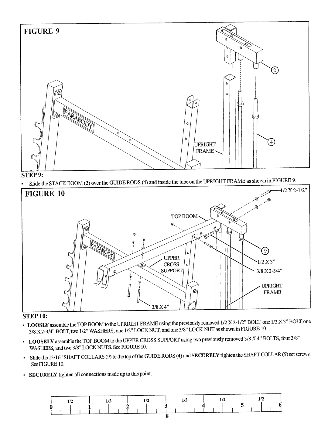
Slide the STACKBOOM(21 over the GUIDERODS (4) and inside the tube on the UPRIGHTFRAMEas shown in FIGURE
FIGURE 10 | |
~¢~ |
"1/2 X 3"
;TEP10:
¯LOOSLYassemble the TOPBOOMto the UPRIGHTFRAMEusing the previously removed1/2 X
¯LOOSELYassemble the T()P BOOMto the UPPERCROSSSUPPORTusing two previously removed 3/8 X 4" BOLTS,four 3/8" WASHERS,and two 3/8" LOCKNUTS.See FIGURE10.
¯Slide the 13/16" SHAFTCOLLARS(9) to the top of the GUIDERODS(4) and SECURELYtighten the SHAFTCOLLAR(9) set screws. See FIGURE10.
¯SECURELYtighten all COlmectionsmadeup to this point.
I | 1/2 | I | 1/2 | I | 1/2 | I | 1/2 | I | 1/2 | I | 1/2 | l |
|
| 6 | ||||||||||
|
|
|
|
|
|
|
|
|
|
|
| |
I t | I | I I | I |
|
| 8 |
|
|
|
|
|
|
|
|
|
|
|
|
|
|
|
|
|
|
