Installing the Network and DTE Cables
"Procedure
To install the cables:
1.Note the location of the 7511 Dual DSU circuit cards in the carrier (Slots 1±8, Slots 9±16, or all slots).
2.Connect network cables to the appropriate NIM and backplane connector according to the following table.
Facing the rear of the carrier, connect a
The NIM on the left side for DSU As on | The NIM on the right side for DSU As on |
7511 cards in Slots 9±16. | 7511 cards in Slots 1±8. |
|
|
Connector P22 for DSU Bs on 7511 | Connector P21 for DSU Bs of 7511 cards |
cards in Slots 9±16. | in Slots 1±8. |
|
|
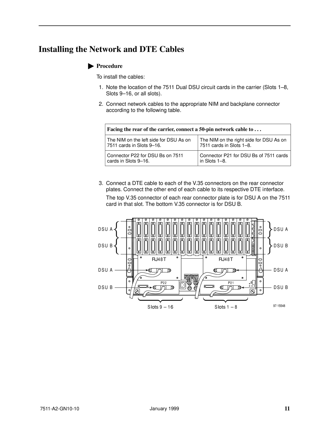
3.Connect a DTE cable to each of the V.35 connectors on the rear connector plates. Connect the other end of each cable to its respective DTE interface.
The top V.35 connector of each rear connector plate is for DSU A on the 7511 card in that slot. The bottom V.35 connector is for DSU B.
D SU A D SU B
D SU A
D SU B
|
| D SU A |
|
| D SU B |
R J48T | R J48T |
|
|
| D SU A |
P 2 2 | P 21 | D SU B |
|
| |
Slots 9 – 16 | Slots 1 – 8 |
January 1999 | 11 |