495-14797
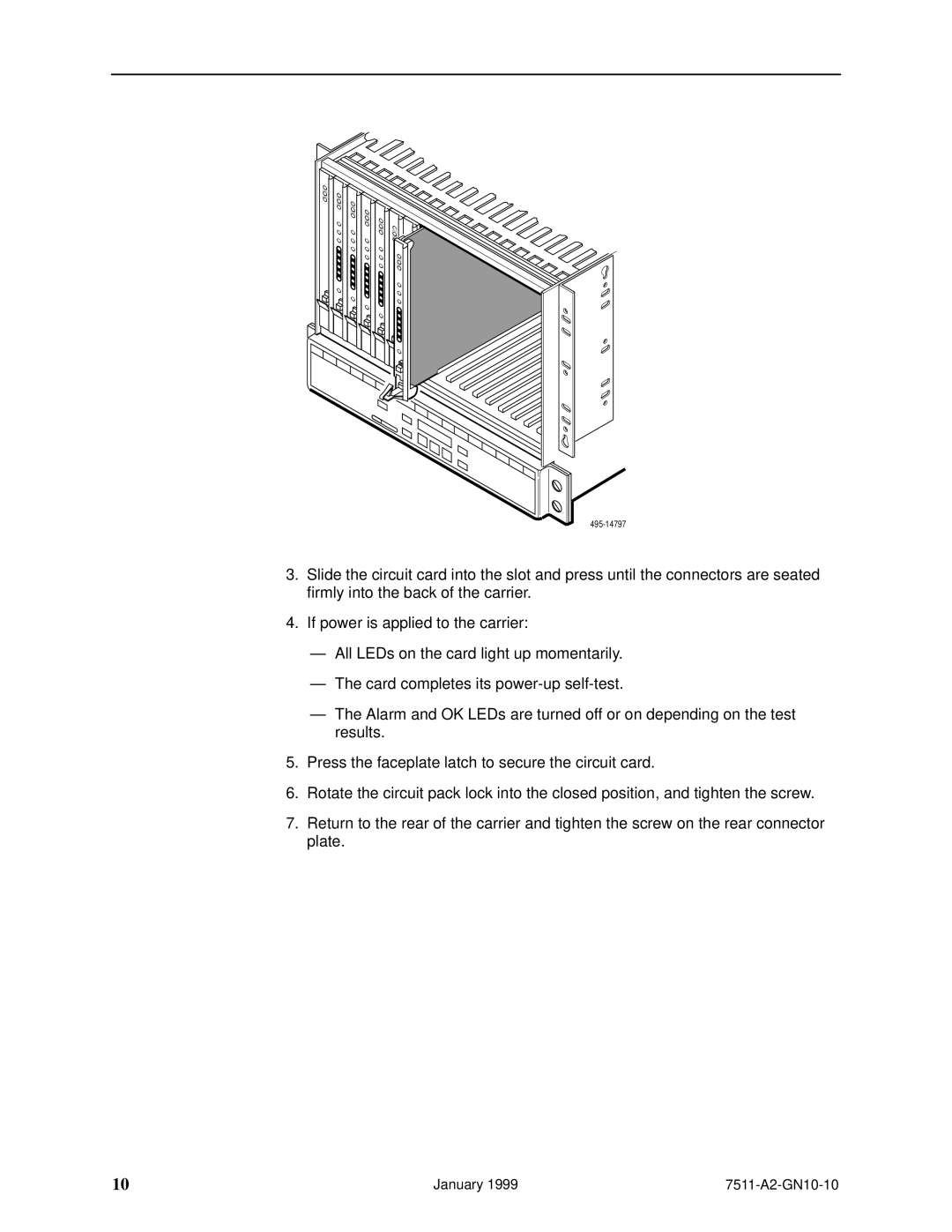
3.Slide the circuit card into the slot and press until the connectors are seated firmly into the back of the carrier.
4.If power is applied to the carrier:
ÐAll LEDs on the card light up momentarily.
ÐThe card completes its
ÐThe Alarm and OK LEDs are turned off or on depending on the test results.
5.Press the faceplate latch to secure the circuit card.
6.Rotate the circuit pack lock into the closed position, and tighten the screw.
7.Return to the rear of the carrier and tighten the screw on the rear connector plate.
10 | January 1999 |