5.3.2 Loops and Patterns
The following section describes the Remote Loopback/BER test modes.
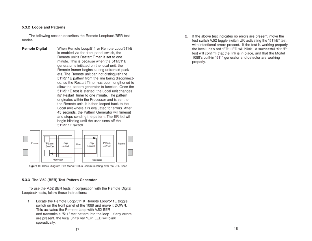
Remote Digital When Remote Loop/511 or Remote Loop/511/E is enabled via the front panel switch, the Remote unit’s Restart Timer is set to one minute. This is because when the 511/511E generator is initiated on the local unit, the Remote framer begins seeing unframed pack- ets. The Remote unit can not distinguish the 511/511E pattern from the line being disconnect- ed, so the Restart Timer has been lengthened to allow the pattern generator to function. Once the 511/511E test is started, the Local unit changes its' Restart Timer to one minute. The pattern originates within the Processor and is sent to the Remote unit. It is then looped back to the Local unit where it is evaluated for errors. After 45 seconds, the Pattern Generator will timeout and stops sending the pattern. The ER led will begin blinking until the user turns off the 511/511E switch.
Framer | Pattern | Loop | Line | Loop | Pattern | Framer |
| Gen/Det | Control | Control | Gen/Det |
| |
|
|
| ||||
| Processor |
| Processor |
|
| |
Figure 9: Block Diagram Two Model 1089s Communicating over the DSL Span
5.3.3 The V.52 (BER) Test Pattern Generator
To use the V.52 BER tests in conjunction with the Remote Digital Loopback tests, follow these instructions:
1.Locate the Remote Loop/511 & Remote Loop/511E toggle switch on the front panel of the 1089 and move it DOWN. This activates the Remote Loop with V.52 BER
and transmits a “511” test pattern into the loop. If any errors are present, the local unit’s red “ER” LED will blink sporadically.
17
2.If the above test indicates no errors are present, move the test switch V.52 toggle switch UP, activating the “511/E” test with intentional errors present. If the test is working properly, the local unit’s red “ER” LED will blink. A successful “511/E” test will confirm that the link is in place, and that the Model 1089’s
18
