4.4 POWER CONNECTION
Universal AC Power (100-240VAC)
The Model 1089 uses a 5VDC, 2A universal input
The Model 1089 powers up as soon as it is plugged into an AC
120 VAC Power (US)
The
230 VAC Power (International)
The 230 VAC adapter supplied with the International version of the Model 1089 is a wall mount type and may be plugged into any approved 230 VAC wall jack.
DC Power
The
|
|
| To Power | |
|
|
|
| Supply Jack |
To |
| |||
Source |
|
|
| |
|
|
|
|
|
|
|
|
|
|
|
| +Vin |
|
|
|
|
|
|
|
Figure 6. Connecting DC Power to the 48V-PSM DC Power Supply.
WARNING! There are no
11
5.0 OPERATION
When the Model 1089 has been properly configured and installed, it should operate transparently. This sections describes
5.1 POWER-UP
Before applying power to the Model 1089, please read Section
4.3and ensure that the unit is connected to the appropriate power source.
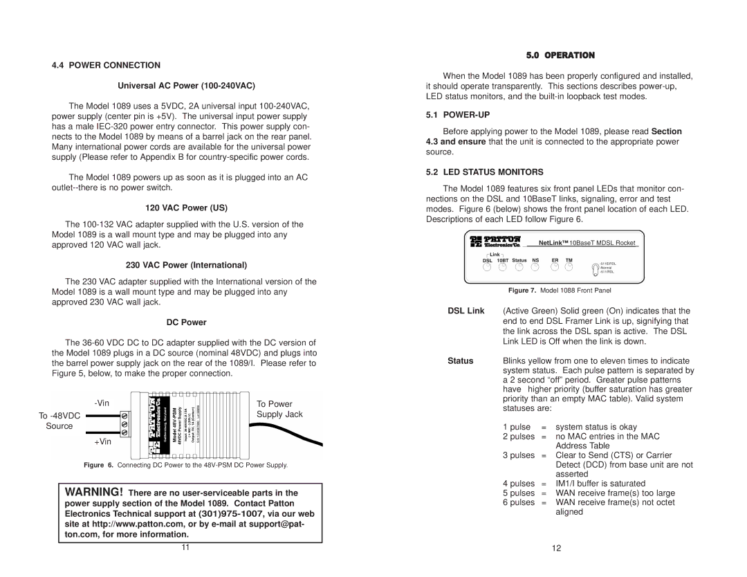
5.2 LED STATUS MONITORS
The Model 1089 features six front panel LEDs that monitor con- nections on the DSL and 10BaseT links, signaling, error and test modes. Figure 6 (below) shows the front panel location of each LED. Descriptions of each LED follow Figure 6.
Figure 7. Model 1088 Front Panel
DSL Link (Active Green) Solid green (On) indicates that the end to end DSL Framer Link is up, signifying that the link across the DSL span is active. The DSL Link LED is Off when the link is down.
Status Blinks yellow from one to eleven times to indicate system status. Each pulse pattern is separated by a 2 second “off” period. Greater pulse patterns have higher priority (buffer saturation has greater priority than an empty MAC table). Valid system statuses are:
1 pulse | = | system status is okay |
2 pulses | = | no MAC entries in the MAC |
|
| Address Table |
3 pulses | = | Clear to Send (CTS) or Carrier |
|
| Detect (DCD) from base unit are not |
|
| asserted |
4 pulses | = | IM1/I buffer is saturated |
5 pulses | = | WAN receive frame(s) too large |
6 pulses | = | WAN receive frame(s) not octet |
|
| aligned |
|
| 12 |