4.0 INSTALLATION
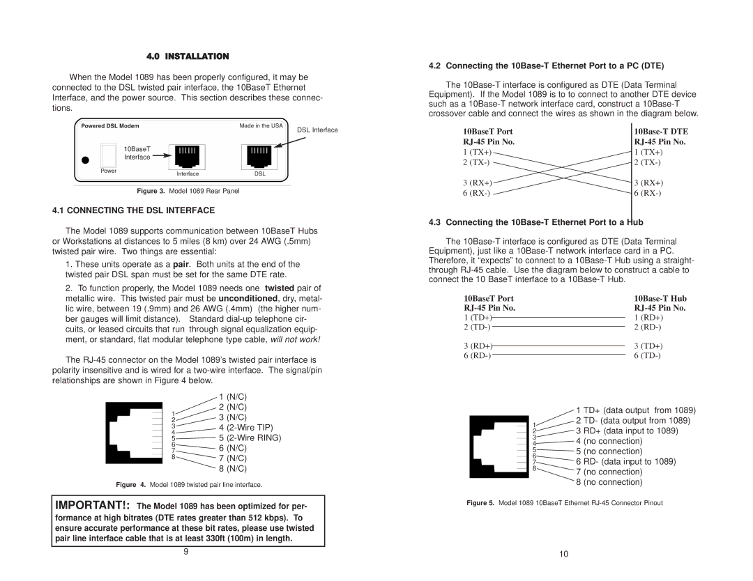
When the Model 1089 has been properly configured, it may be connected to the DSL twisted pair interface, the 10BaseT Ethernet Interface, and the power source. This section describes these connec- tions.
4.2 Connecting the 10Base-T Ethernet Port to a PC (DTE)
The
DSL Interface
10BaseT Interface ![]()
Figure 3. Model 1089 Rear Panel
4.1 CONNECTING THE DSL INTERFACE
10BaseT Port
1(TX+)
2
3(RX+)
6
10Base-T DTE RJ-45 Pin No.
1(TX+)
2
3(RX+)
6
The Model 1089 supports communication between 10BaseT Hubs or Workstations at distances to 5 miles (8 km) over 24 AWG (.5mm) twisted pair wire. Two things are essential:
1.These units operate as a pair. Both units at the end of the twisted pair DSL span must be set for the same DTE rate.
2.To function properly, the Model 1089 needs one twisted pair of metallic wire. This twisted pair must be unconditioned, dry, metal- lic wire, between 19 (.9mm) and 26 AWG (.4mm) (the higher num- ber gauges will limit distance). Standard
The
4.3 Connecting the 10Base-T Ethernet Port to a Hub
The
10BaseT Port |
|
|
|
| ||||
|
|
|
| |||||
1 | (TD+) |
|
|
| 1 | (RD+) | ||
|
|
| ||||||
2 |
|
| 2 | |||||
|
| |||||||
3 | (RD+) |
|
| 3 | (TD+) | |||
|
| |||||||
6 |
|
|
|
| 6 | |||
|
|
|
| |||||
| 1 (N/C) | |
1 | 2 (N/C) | |
3 (N/C) | ||
2 | ||
3 |
|
1
1 TD+ (data output from 1089)
2 TD- (data output from 1089)
4 | 4 |
55
6 | 6 (N/C) |
7 | |
8 | 7 (N/C) |
8 (N/C)
Figure 4. Model 1089 twisted pair line interface.
IMPORTANT!: The Model 1089 has been optimized for per- formance at high bitrates (DTE rates greater than 512 kbps). To ensure accurate performance at these bit rates, please use twisted pair line interface cable that is at least 330ft (100m) in length.
9
23 RD+ (data input to 1089)
3
4![]() 4 (no connection)
4 (no connection)
5![]() 5 (no connection)
5 (no connection)
6
76 RD- (data input to 1089)
87 (no connection)
8 (no connection)
Figure 5. Model 1089 10BaseT Ethernet RJ-45 Connector Pinout
10