5.3.2 Loops and Patterns
The following section describes the Test Modes used in the Model 1095. At the bottom of each Test Mode, a figure is included to show the data path.
Local Loop | There are two different modes of operation for a |
Framer | Pattern | Loop |
| Gen/Det | Control |
| Processor | |
Line
Loop Pattern
Control Gen/Det
Processor
Framer
Local Loop depending on the status of the units |
at the time that the Local Loop is initiated. If the |
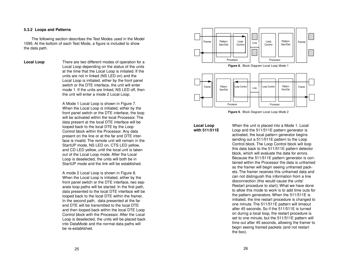
Figure 8. Block Diagram Local Loop Mode 1
units are not in linked (NS LED on) and the |
Local Loop is initiated, either by the front panel |
switch or the DTE interface, the unit will enter |
mode 1. If the units are linked, NS LED off, then |
the unit will enter a mode 2 Local Loop. |
A Mode 1 Local Loop is shown in Figure 7. |
When the Local Loop is initiated, either by the |
Framer |
Pattern | Loop Control | Line | Loop Control | Pattern | Framer |
Gen/Det |
| Gen/Det |
| ||
|
|
| |||
| Processor |
| Processor |
|
|
front panel switch or the DTE interface, the loop |
will be activated within the local Processor. The |
data present at the local DTE interface will be |
looped back to the local DTE by the Loop |
Control block within the Processor. Any data |
present on the line or at the far end DTE inter- |
face is invalid. The remote unit will remain in the |
StartUP mode, NS LED on, CTS LED yellow, |
and CD LED yellow, until the local unit is taken |
out of the Local Loop mode. After the Local |
Loop is deselected, the units will both be in |
StartUP mode and the link will be established. |
A mode 2 Local Loop is shown in Figure 8. |
When the Local Loop is initiated, either by the |
front panel switch or the DTE interface, two sep- |
arate loop paths will be started. In the first path, |
data presented to the local DTE interface will be |
looped back to the local DTE within the framer. |
In the second path, data presented at the far |
end DTE will be transmitted to the local DTE |
and then looped back within the local DTE Loop |
Control block with the Processor. After the Local |
Loop is deselected, the units will be placed back |
into DataMode and the normal data paths will |
be |
25
| Figure 9. Block Diagram Local Loop Mode 2 |
Local Loop | When the unit is placed into a Mode 1. Local |
with 511/511E | Loop and the 511/511E pattern generator is |
| activated, the local pattern generator begins |
| sending out a 511/511E pattern to the Loop |
| Control block. The Loop Control block will loop |
| this data back to the 511/511E pattern detector |
| block, which will evaluate the data for errors. |
| Because the 511/511E pattern generator is con- |
| tained within the Processor the data is unframed |
| so the framer will begin seeing unframed pack- |
| ets. The framer receives this unframed data and |
| can not distinguish this information from a line |
| disconnection (this would cause the units' |
| Restart procedure to start). What we have done |
| to allow this mode to work is to add time outs for |
| the pattern generators. When the 511/511E is |
| initiated, the line restart procedure is changed to |
| one minute. The 511/511E pattern will timeout |
| after 45 seconds. So if the 511/511E is turned |
| on during a local loop, the restart procedure is |
| set to one minute, but the 511/511E pattern will |
| time out after 45 seconds, allowing the framer to |
| begin seeing framed packets (and not restart |
| the box). |
| 26 |