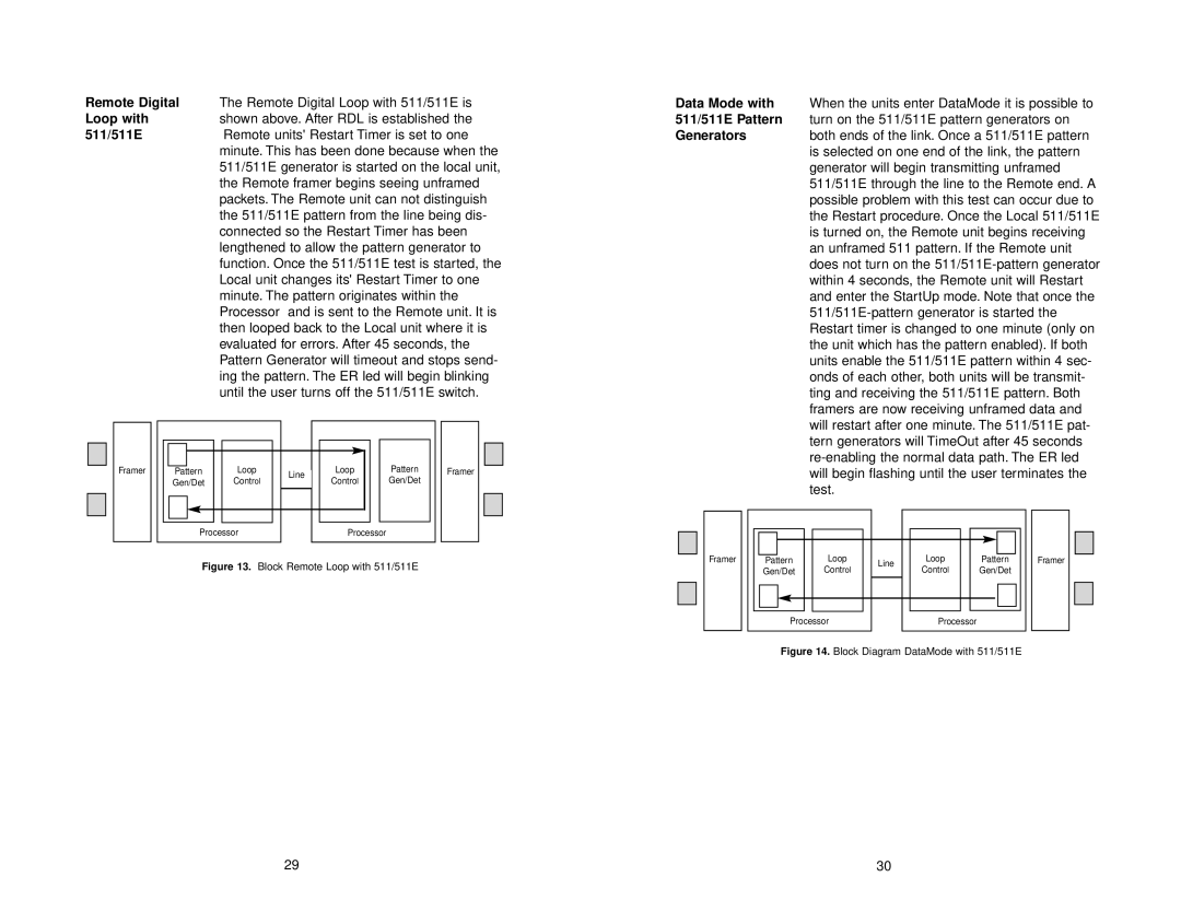
Remote Digital | The Remote Digital Loop with 511/511E is |
Loop with | shown above. After RDL is established the |
511/511E | Remote units' Restart Timer is set to one |
| minute. This has been done because when the |
| 511/511E generator is started on the local unit, |
| the Remote framer begins seeing unframed |
| packets. The Remote unit can not distinguish |
| the 511/511E pattern from the line being dis- |
| connected so the Restart Timer has been |
| lengthened to allow the pattern generator to |
| function. Once the 511/511E test is started, the |
| Local unit changes its' Restart Timer to one |
| minute. The pattern originates within the |
| Processor and is sent to the Remote unit. It is |
| then looped back to the Local unit where it is |
| evaluated for errors. After 45 seconds, the |
| Pattern Generator will timeout and stops send- |
| ing the pattern. The ER led will begin blinking |
| until the user turns off the 511/511E switch. |
Framer | Pattern | Loop | Line | Loop | Pattern | Framer |
| Gen/Det | Control | Control | Gen/Det |
| |
|
|
| ||||
| Processor |
| Processor |
|
| |
Figure 13. Block Remote Loop with 511/511E
Data Mode with When the units enter DataMode it is possible to
511/511E Pattern turn on the 511/511E pattern generators on
Generatorsboth ends of the link. Once a 511/511E pattern is selected on one end of the link, the pattern generator will begin transmitting unframed 511/511E through the line to the Remote end. A possible problem with this test can occur due to the Restart procedure. Once the Local 511/511E is turned on, the Remote unit begins receiving an unframed 511 pattern. If the Remote unit does not turn on the
Framer | Pattern | Loop | Line | Loop | Pattern | Framer |
| Gen/Det | Control | Control | Gen/Det |
| |
|
|
|
Processor |
| Processor |
Figure 14. Block Diagram DataMode with 511/511E
29 | 30 |
