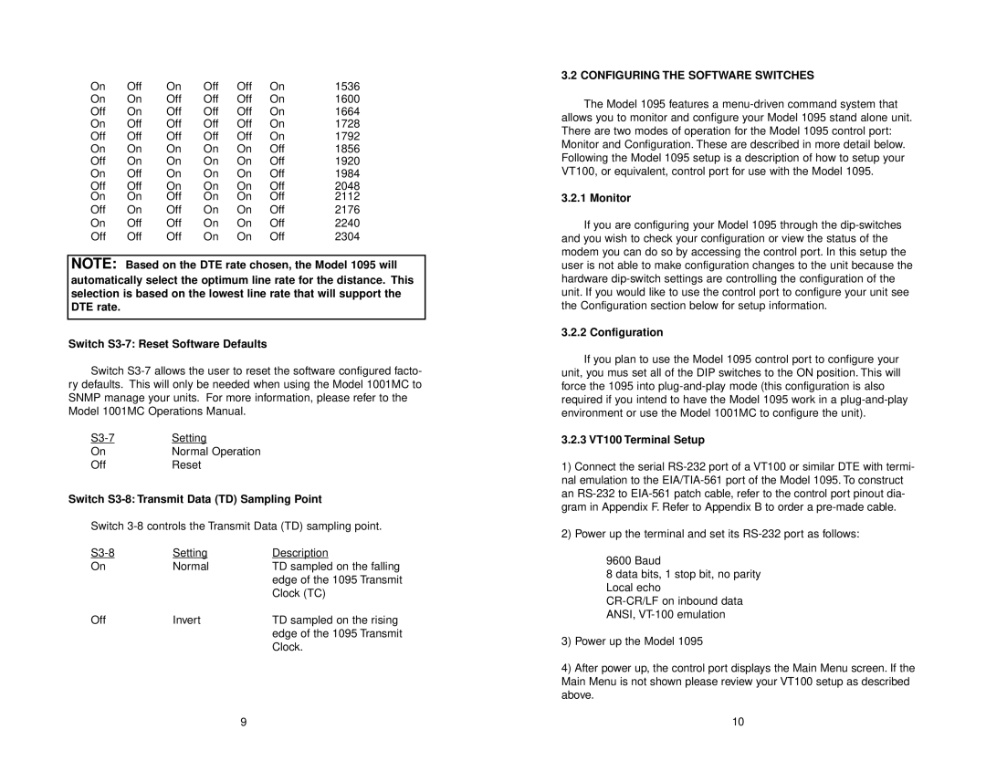
Patton electronic 1095 user manual Configuring the Software Switches

Models: 1095

1 20
Download 20 pages 15.53 Kb
Page 6
Image 6

On

Off

On

Off

Off

On

1536

On

On

Off

Off

Off

On

1600

Off

On

Off

Off

Off

On

1664

On

Off

Off

Off

Off

On

1728

Off

Off

Off

Off

Off

On

1792

On

On

On

On

On

Off

1856

Off

On

On

On

On

Off

1920

On

Off

On

On

On

Off

1984

Off

Off

On

On

On

Off

2048

On

On

Off

On

On

Off

2112

Off

On

Off

On

On

Off

2176

On

Off

Off

On

On

Off

2240

Off

Off

Off

On

On

Off

2304

NOTE: Based on the DTE rate chosen, the Model 1095 will automatically select the optimum line rate for the distance. This selection is based on the lowest line rate that will support the DTE rate.

Switch S3-7: Reset Software Defaults

Switch S3-7 allows the user to reset the software configured facto- ry defaults. This will only be needed when using the Model 1001MC to SNMP manage your units. For more information, please refer to the Model 1001MC Operations Manual.

S3-7

Setting

On

Normal Operation

Off

Reset

Switch S3-8: Transmit Data (TD) Sampling Point

Switch 3-8 controls the Transmit Data (TD) sampling point.

S3-8

Setting

Description

On

Normal

TD sampled on the falling


edge of the 1095 Transmit


Clock (TC)

Off

Invert

TD sampled on the rising


edge of the 1095 Transmit


Clock.

9

3.2 CONFIGURING THE SOFTWARE SWITCHES

The Model 1095 features a menu-driven command system that allows you to monitor and configure your Model 1095 stand alone unit. There are two modes of operation for the Model 1095 control port: Monitor and Configuration. These are described in more detail below. Following the Model 1095 setup is a description of how to setup your VT100, or equivalent, control port for use with the Model 1095.

3.2.1 Monitor

If you are configuring your Model 1095 through the dip-switches and you wish to check your configuration or view the status of the modem you can do so by accessing the control port. In this setup the user is not able to make configuration changes to the unit because the hardware dip-switch settings are controlling the configuration of the unit. If you would like to use the control port to configure your unit see the Configuration section below for setup information.

3.2.2 Configuration

If you plan to use the Model 1095 control port to configure your unit, you mus set all of the DIP switches to the ON position. This will force the 1095 into plug-and-play mode (this configuration is also required if you intend to have the Model 1095 work in a plug-and-play environment or use the Model 1001MC to configure the unit).

3.2.3 VT100 Terminal Setup

1)Connect the serial RS-232 port of a VT100 or similar DTE with termi- nal emulation to the EIA/TIA-561 port of the Model 1095. To construct an RS-232 to EIA-561 patch cable, refer to the control port pinout dia- gram in Appendix F. Refer to Appendix B to order a pre-made cable.

2)Power up the terminal and set its RS-232 port as follows:

9600 Baud

8 data bits, 1 stop bit, no parity Local echo

CR-CR/LF on inbound data ANSI, VT-100 emulation

3)Power up the Model 1095

4)After power up, the control port displays the Main Menu screen. If the Main Menu is not shown please review your VT100 setup as described above.

10

Page 6
Image 6
Patton electronic 1095 user manual Configuring the Software Switches