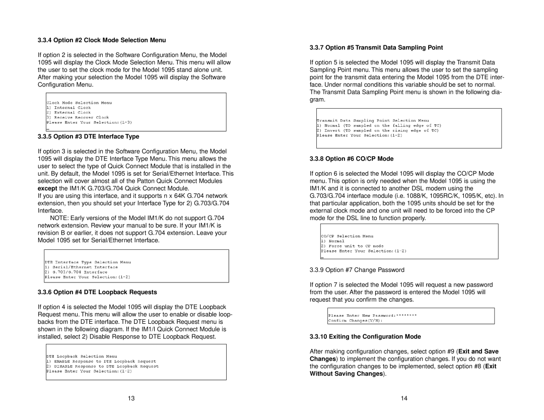
3.3.4 Option #2 Clock Mode Selection Menu
If option 2 is selected in the Software Configuration Menu, the Model 1095 will display the Clock Mode Selection Menu. This menu will allow the user to set the clock mode for the Model 1095 stand alone unit. After making your selection the Model 1095 will display the Software Configuration Menu.
3.3.5 Option #3 DTE Interface Type
If option 3 is selected in the Software Configuration Menu, the Model 1095 will display the DTE Interface Type Menu. This menu allows the user to select the type of Quick Connect Module that is installed in the unit. By default, the Model 1095 is set for Serial/Ethernet Interface. This selection will cover almost all of the Patton Quick Connect Modules except the IM1/K G.703/G.704 Quick Connect Module.
If you are using this interface, and it supports n x 64K G.704 network extension, then you should set your Interface Type for 2) G.703/G.704 Interface.
NOTE: Early versions of the Model IM1/K do not support G.704 network extension. Review your manual to be sure. If your IM1/K is revision B or earlier, it does not support G.704 extension. Leave your Model 1095 set for Serial/Ethernet Interface.
3.3.6 Option #4 DTE Loopback Requests
If option 4 is selected the Model 1095 will display the DTE Loopback Request menu. This menu will allow the user to enable or disable loop- backs from the DTE interface. The DTE Loopback Request menu is shown in the following diagram. If the IM1/I Quick Connect Module is installed, select 2) Disable Response to DTE Loopback Request.
3.3.7 Option #5 Transmit Data Sampling Point
If option 5 is selected the Model 1095 will display the Transmit Data Sampling Point menu. This menu allows the user to set the sampling point for the transmit data entering the Model 1095 from the DTE inter- face. Under normal conditions this variable should be set to normal. The Transmit Data Sampling Point menu is shown in the following dia- gram.
3.3.8 Option #6 CO/CP Mode
If option 6 is selected the Model 1095 will display the CO/CP Mode menu. This option is only needed when the Model 1095 is using the IM1/K and it is connected to another DSL modem using the G.703/G.704 interface module (i.e. 1088/K, 1095RC/K, 1095/K, etc). In that particular application, both the 1095 units should be set for the external clock mode and one unit will need to be forced into the CP mode for the DSL line to function properly.
3.3.9 Option #7 Change Password
If option 7 is selected the Model 1095 will request a new password from the user. After the password is entered the Model 1095 will request that you confirm the changes.
3.3.10 Exiting the Configuration Mode
After making configuration changes, select option #9 (Exit and Save Changes) to implement the configuration changes. If you do not want the configuration changes to be implemented, select option #8 (Exit Without Saving Changes).
13 | 14 |