5.0 OPERATION
Once the Model 1095 is properly configured and installed, it should operate transparently. This sections describes
5.1 POWER-UP
To apply power to the Model 1095, first be sure that you have read Section 4.3, and that the unit is connected to the appropriate power source. Then
5.2 LED STATUS MONITORS
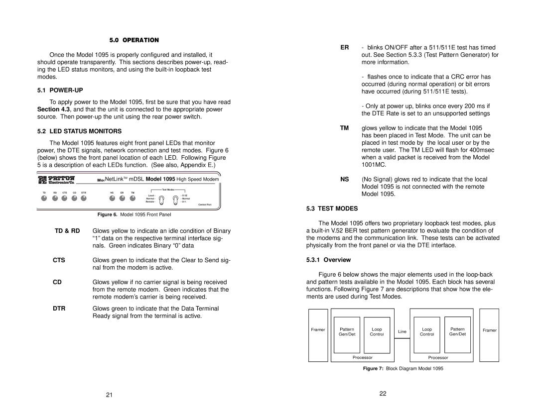
The Model 1095 features eight front panel LEDs that monitor power, the DTE signals, network connection and test modes. Figure 6 (below) shows the front panel location of each LED. Following Figure 5 is a description of each LEDs function. (See also, Appendix E.)
ModelNetLinkTM mDSL Model 1095 High Speed Modem
|
|
|
|
|
|
|
| Test Modes |
TD | RD | CTS | CD | DTR | NS | ER | TM |
|
|
|
|
|
|
|
| Local - | - 511E |
|
|
|
|
|
|
| Normal - | - Normal |
|
|
|
|
|
|
| Remote - | - 511 |
| Control Port |
| Figure 6. Model 1095 Front Panel |
TD & RD | Glows yellow to indicate an idle condition of Binary |
| “1” data on the respective terminal interface sig- |
| nals. Green indicates Binary “0” data |
CTS | Glows green to indicate that the Clear to Send sig- |
| nal from the modem is active. |
CD | Glows yellow if no carrier signal is being received |
| from the remote modem. Green indicates that the |
| remote modem’s carrier is being received. |
DTR | Glows green to indicate that the Data Terminal |
| Ready signal from the terminal is active. |
ER - blinks ON/OFF after a 511/511E test has timed out. See Section 5.3.3 (Test Pattern Generator) for more information.
-flashes once to indicate that a CRC error has occurred (during normal operation) or bit errors have occurred (during 511/511E tests).
-Only at power up, blinks once every 200 ms if the DTE Rate is set to an unsupported settings
TM glows yellow to indicate that the Model 1095 has been placed in Test Mode. The unit can be placed in test mode by the local user or by the remote user. The TM LED will flash for 400msec when a valid packet is received from the Model 1001MC.
NS (No Signal) glows red to indicate that the local Model 1095 is not connected with the remote Model 1095.
5.3 TEST MODES
The Model 1095 offers two proprietary loopback test modes, plus a
5.3.1 Overview
Figure 6 below shows the major elements used in the loop-back and pattern tests available in the Model 1095. Each block has several functions. Following Figure 7 are descriptions that show how the ele- ments are used during Test Modes.
|
|
|
|
|
|
|
|
|
|
|
|
|
|
|
|
|
|
|
|
|
|
|
|
|
|
| Pattern |
| Loop |
|
|
|
| Loop |
|
| Pattern |
|
|
|
| ||||
Framer |
|
|
|
|
|
|
|
|
|
|
|
|
| Framer | ||||||||
|
|
|
|
|
| Line |
|
|
|
|
|
| ||||||||||
|
|
|
| Gen/Det |
| Control |
|
|
| Control |
|
| Gen/Det |
|
|
|
| |||||
|
|
|
|
|
|
|
|
|
|
|
|
|
| |||||||||
|
|
|
|
|
|
|
|
|
|
|
|
|
|
| ||||||||
|
|
|
|
|
|
|
|
|
|
|
|
|
|
| ||||||||
|
|
|
|
|
|
|
|
|
|
|
|
|
|
|
|
|
|
|
|
|
|
|
|
|
|
|
|
|
|
|
|
|
|
|
|
|
|
|
|
|
|
|
|
|
|
|
|
|
|
|
|
|
|
|
|
|
|
|
|
|
|
| ||||||
|
|
|
|
| Processor |
|
|
| Processor |
|
|
|
|
|
| |||||||
|
|
|
|
|
|
|
|
|
|
|
|
|
|
|
|
|
|
|
|
|
|
|
Figure 7: Block Diagram Model 1095
21 | 22 |