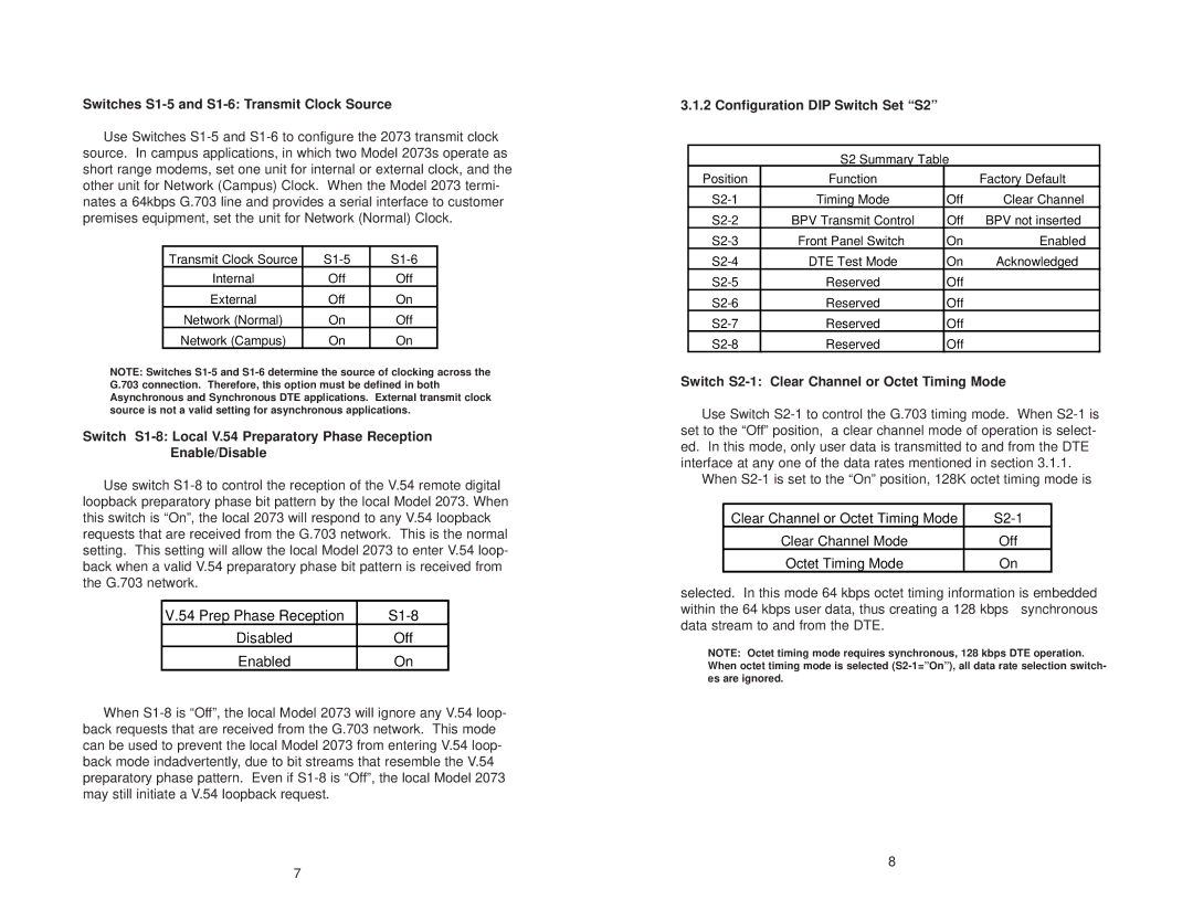
2073 specifications
The Patton Electronic 2073 is a cutting-edge telecommunications device that represents a pivotal advancement in the realm of data transmission and connectivity. This versatile piece of equipment is engineered for use in various networking environments, providing a robust solution for organizations that demand reliability and advanced functionality.One of the hallmark features of the Patton 2073 is its support for both traditional TDM (Time Division Multiplexing) and modern VoIP (Voice over Internet Protocol) technologies. This dual capability allows businesses to integrate their existing telephony systems with newer IP-based networks seamlessly, ensuring a smooth transition to evolved communication methods without sacrificing legacy connections.
The device boasts a user-friendly interface which simplifies setup and management. The intuitive configuration options empower users to easily adjust settings according to specific operational needs. Additionally, the web-based management tools provide remote access and monitoring capabilities, reducing the time and resources needed for troubleshooting and maintenance.
With advanced security features, the Patton 2073 protects data integrity and privacy. Encrypted communication protocols safeguard sensitive information during transmission, making it a reliable choice for organizations that prioritize data security, especially in sensitive industries such as finance and healthcare.
Moreover, the Patton 2073 features a high level of versatility, supporting multiple different network connection types. It can accommodate various protocols like E1, T1, and Ethernet interfaces, allowing for flexible deployment options in a myriad of setups. This adaptability ensures that businesses can continue to grow and scale their communication networks without overhauling their existing infrastructure.
The device is also designed with efficiency in mind, featuring low power consumption and a compact form factor, which makes it easy to integrate into existing network cabinets or setups. Its robust construction ensures durability and longevity, providing organizations with a dependable solution that can withstand everyday operational challenges.
In conclusion, the Patton Electronic 2073 distinguishes itself through its blend of legacy support, advanced features, user-friendly design, and robust security measures. It is an essential tool for modern organizations seeking to improve their telecommunications infrastructure while maintaining high operational standards.

