5.0 OPERATION

Once the Model 2073 is properly configured and installed, it should operate transparently. This sections describes power-up, read- ing the LED status monitors, and using the built-in loopback test modes.

5.1 POWER-UP

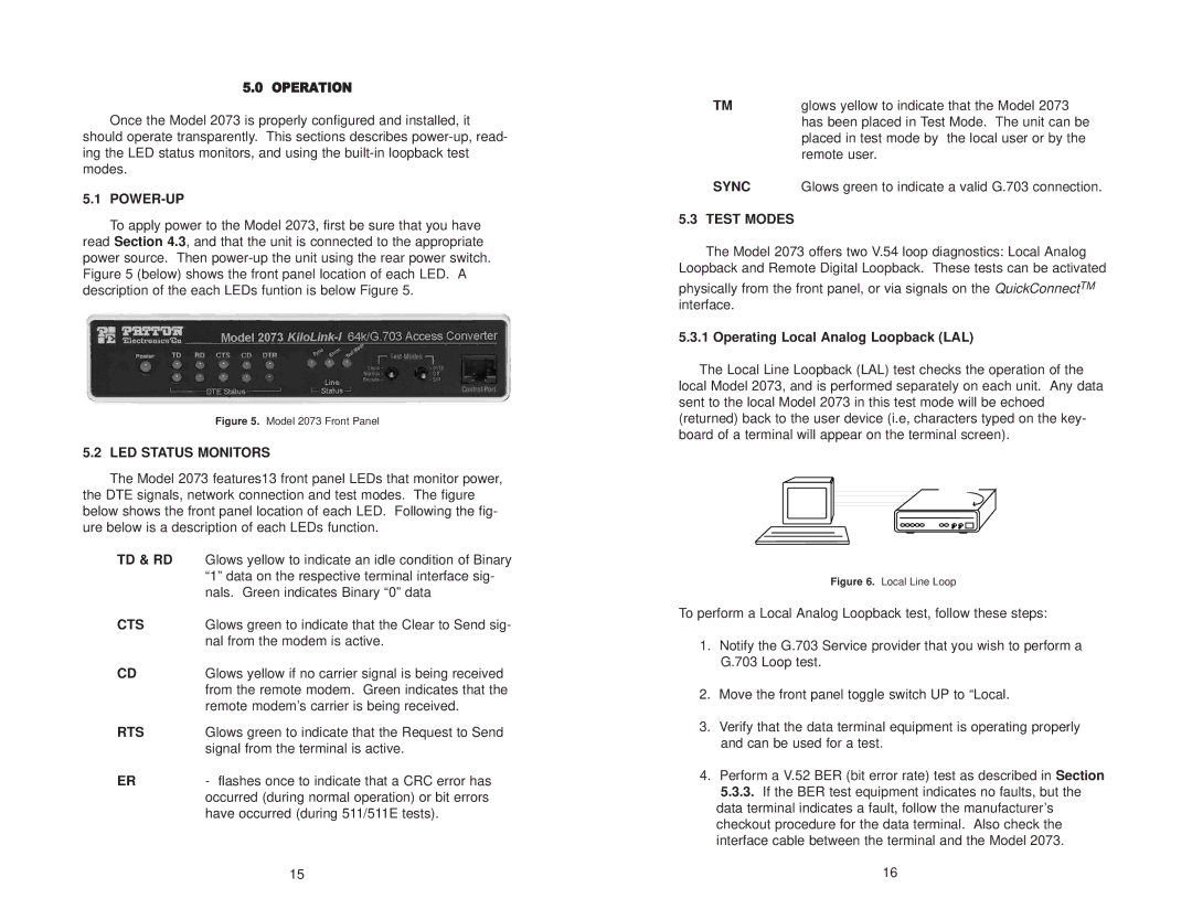
To apply power to the Model 2073, first be sure that you have read Section 4.3, and that the unit is connected to the appropriate power source. Then power-up the unit using the rear power switch. Figure 5 (below) shows the front panel location of each LED. A description of the each LEDs funtion is below Figure 5.

Figure 5. Model 2073 Front Panel

5.2 LED STATUS MONITORS

The Model 2073 features13 front panel LEDs that monitor power, the DTE signals, network connection and test modes. The figure below shows the front panel location of each LED. Following the fig- ure below is a description of each LEDs function.

TD & RD

Glows yellow to indicate an idle condition of Binary


“1” data on the respective terminal interface sig-


nals. Green indicates Binary “0” data

CTS

Glows green to indicate that the Clear to Send sig-


nal from the modem is active.

CD

Glows yellow if no carrier signal is being received


from the remote modem. Green indicates that the


remote modem’s carrier is being received.

RTS

Glows green to indicate that the Request to Send


signal from the terminal is active.

ER

- flashes once to indicate that a CRC error has


occurred (during normal operation) or bit errors


have occurred (during 511/511E tests).


15

TM

glows yellow to indicate that the Model 2073


has been placed in Test Mode. The unit can be


placed in test mode by the local user or by the


remote user.

SYNC

Glows green to indicate a valid G.703 connection.

5.3 TEST MODES

The Model 2073 offers two V.54 loop diagnostics: Local Analog Loopback and Remote Digital Loopback. These tests can be activated

physically from the front panel, or via signals on the QuickConnectTM interface.

5.3.1 Operating Local Analog Loopback (LAL)

The Local Line Loopback (LAL) test checks the operation of the

local Model 2073, and is performed separately on each unit. Any data sent to the local Model 2073 in this test mode will be echoed (returned) back to the user device (i.e, characters typed on the key- board of a terminal will appear on the terminal screen).

1090

1090

Figure 6. Local Line Loop

To perform a Local Analog Loopback test, follow these steps:

1.Notify the G.703 Service provider that you wish to perform a G.703 Loop test.

2.Move the front panel toggle switch UP to “Local.

3.Verify that the data terminal equipment is operating properly and can be used for a test.

4.Perform a V.52 BER (bit error rate) test as described in Section

5.3.3.If the BER test equipment indicates no faults, but the data terminal indicates a fault, follow the manufacturer’s checkout procedure for the data terminal. Also check the interface cable between the terminal and the Model 2073.

16

Page 9
Image 9
Patton electronic 2073 user manual Power-Up, LED Status Monitors, Td & Rd, Cts, Rts, Sync, Test Modes

2073 specifications

The Patton Electronic 2073 is a cutting-edge telecommunications device that represents a pivotal advancement in the realm of data transmission and connectivity. This versatile piece of equipment is engineered for use in various networking environments, providing a robust solution for organizations that demand reliability and advanced functionality.

One of the hallmark features of the Patton 2073 is its support for both traditional TDM (Time Division Multiplexing) and modern VoIP (Voice over Internet Protocol) technologies. This dual capability allows businesses to integrate their existing telephony systems with newer IP-based networks seamlessly, ensuring a smooth transition to evolved communication methods without sacrificing legacy connections.

The device boasts a user-friendly interface which simplifies setup and management. The intuitive configuration options empower users to easily adjust settings according to specific operational needs. Additionally, the web-based management tools provide remote access and monitoring capabilities, reducing the time and resources needed for troubleshooting and maintenance.

With advanced security features, the Patton 2073 protects data integrity and privacy. Encrypted communication protocols safeguard sensitive information during transmission, making it a reliable choice for organizations that prioritize data security, especially in sensitive industries such as finance and healthcare.

Moreover, the Patton 2073 features a high level of versatility, supporting multiple different network connection types. It can accommodate various protocols like E1, T1, and Ethernet interfaces, allowing for flexible deployment options in a myriad of setups. This adaptability ensures that businesses can continue to grow and scale their communication networks without overhauling their existing infrastructure.

The device is also designed with efficiency in mind, featuring low power consumption and a compact form factor, which makes it easy to integrate into existing network cabinets or setups. Its robust construction ensures durability and longevity, providing organizations with a dependable solution that can withstand everyday operational challenges.

In conclusion, the Patton Electronic 2073 distinguishes itself through its blend of legacy support, advanced features, user-friendly design, and robust security measures. It is an essential tool for modern organizations seeking to improve their telecommunications infrastructure while maintaining high operational standards.