Patton electronic 2703-X21 user manual S1-2 and S1-3 Rate Adaptation, S1-4 Loopback Test Enable

Models: 2703-X21

1 10
Download 10 pages 44.16 Kb
Page 4
Image 4
S1-2 and S1-3: Rate Adaptation

S1-2 and S1-3: Rate Adaptation

Switches S1-2 and S1-3 are set in combination to allow the Model

2703-X21 to adapt to terminal devices running at data rates of less than 2.048 Mbps (The network rate remains 2.048 Mbps regardless of the terminal rate adaptation setting). The setting you select should match the data rate of your terminal device.

S1-2

S1-3

Setting

Off

Off

2.048 Mbps

On

Off

1.024 Mbps

Off

On

512 kbps

On

On

256 kbps

NOTE: Revision B Firmware (or newer, Implemented 6/19/98) has been adopted to correct signal polarity at 1.024 Mbps, 512 kbps, and 256kbps. To operate Revision B Firmware units with Revision A (or older) units at one of these sub-rates, you must invert invert the data (Switch S1-5 On. See Below) (Firmware revision level is printed on the label on the bottom of the unit).

S1-4: Loopback Test Enable

Depending upon the setting of switch S1-4 the Model 2703-X21 will either be continually in loopback mode, or loopback mode will be enabled by pressing and holding the front panel switch. Since the front panel switch is spring loaded–it returns to “Normal” operation when pressure is released–this DIP switch provides a way of leaving the Model 2703-X21 in “unattended” loopback mode for remote test purposes.

S1-4

Setting

On

Continual “unattended” loopback mode

Off

Loopback activation by front panel switch

S1-5: Data Inversion

The setting for switch S1-5 determines whether or not the data

stream from the local DTE is inverted within the Model 2703-X21 before being passed to the G.703 network. The ability to invert the data stream may be necessary when the Model 2703-X21 is being used with an embedded G.703 device that inverts the data on the remote end. Normally, data inversion is not necessary.

S1-5

Setting

On

Data inverted

Off

Data not inverted

S1-6, S1-7 & S1-8 Not Used

5

3.2 INTERNAL JUMPER SETTINGS

The Model 2703-X21’s seven jumpers are located on the PC board inside the unit. To access the jumpers, follow these instructions:

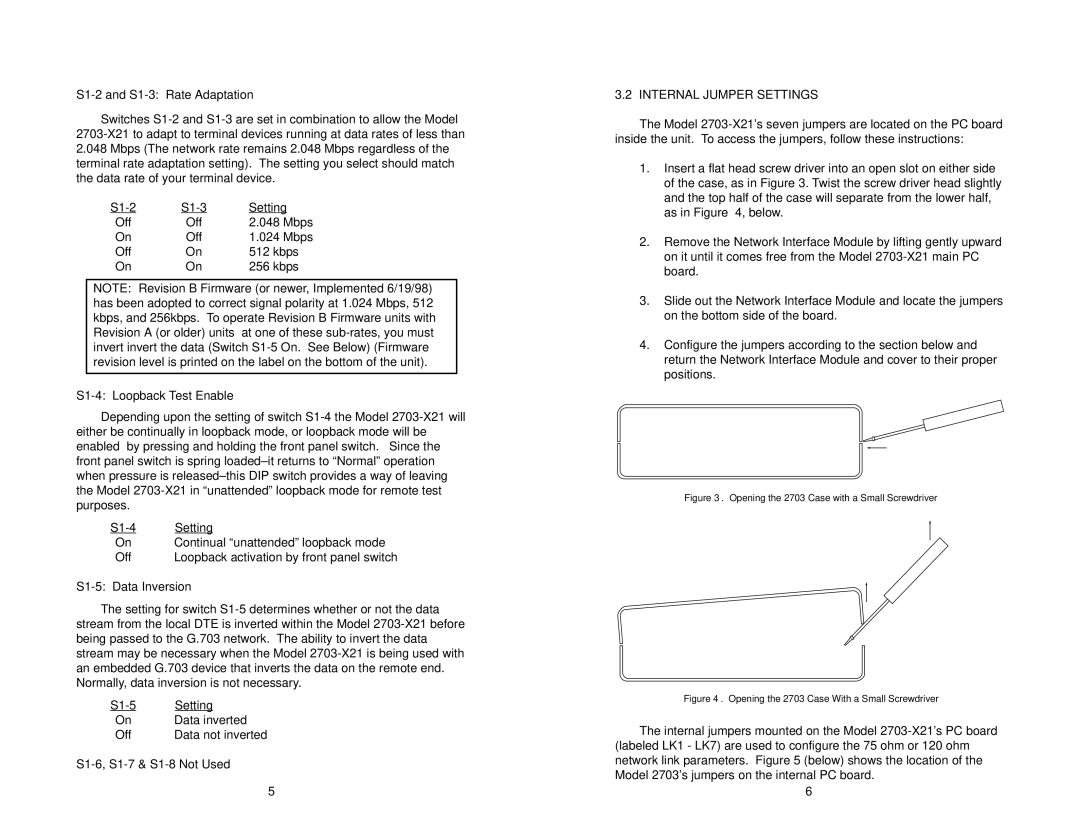
1.Insert a flat head screw driver into an open slot on either side of the case, as in Figure 3. Twist the screw driver head slightly and the top half of the case will separate from the lower half, as in Figure 4, below.

2.Remove the Network Interface Module by lifting gently upward on it until it comes free from the Model 2703-X21 main PC board.

3.Slide out the Network Interface Module and locate the jumpers on the bottom side of the board.

4.Configure the jumpers according to the section below and return the Network Interface Module and cover to their proper positions.

Figure 3. Opening the 2703 Case with a Small Screwdriver

Figure 4. Opening the 2703 Case With a Small Screwdriver

The internal jumpers mounted on the Model 2703-X21’s PC board (labeled LK1 - LK7) are used to configure the 75 ohm or 120 ohm network link parameters. Figure 5 (below) shows the location of the Model 2703’s jumpers on the internal PC board.

6

Page 4
Image 4
Patton electronic 2703-X21 user manual S1-2 and S1-3 Rate Adaptation, S1-4 Loopback Test Enable, S1-5 Data Inversion