Model 4520 & 4110 Series Getting Started Guide | 1 • General information |
|
|
Ports descriptions
The SmartNode 4110 Series rear panel ports are described in table 4.
|
|
|
|
|
|
|
|
|
| Table 4. Rear panel ports | ||||||||||||||||||||||
|
|
|
|
|
|
|
|
|
|
|
|
|
|
|
|
|
|
|
|
|
|
|
|
|
|
|
|
|
|
|
|
|
Port |
| Location |
|
|
|
| Description | |||||||||||||||||||||||||
|
|
|
|
|
|
|
|
|
|
|
|
|
|
|
|
|
|
|
|
|
|
|
|
|
|
|
|
|
|
|
|
|
10/100 Ethernet | Rear panel | |||||||||||||||||||||||||||||||
ETH 0/0 |
|
|
|
|
|
|
|
| Ethernet device (a cable or DSL modem, LAN hub or switch, for example). | |||||||||||||||||||||||
|
|
|
|
|
|
|
|
|
|
|
|
|
|
|
|
|
|
|
|
|
|
|
|
|
|
|
|
|
|
|
|
|
Voice Ports, FXS | Rear panel | FXS | ||||||||||||||||||||||||||||||
|
|
|
|
|
|
|
|
| with an FXO port (a telephone for example). EuroPOTS support (ETSI | |||||||||||||||||||||||
|
|
|
|
|
|
|
|
| EG201 188). Configured per model as follows: | |||||||||||||||||||||||
|
|
|
|
|
|
|
|
| • Model | |||||||||||||||||||||||
|
|
|
|
|
|
|
|
| • Model | |||||||||||||||||||||||
|
|
|
|
|
|
|
|
| • Model | |||||||||||||||||||||||
|
|
|
|
|
|
|
|
| • Model | |||||||||||||||||||||||
|
|
|
|
|
|
|
|
|
|
|
|
|
|
|
|
|
|
|
|
|
|
|
|
|
|
|
|
|
|
|
|
|
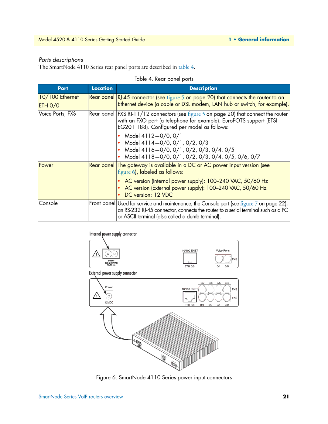
Power | Rear panel | The gateway is available in a DC or AC power input version (see | ||||||||||||||||||||||||||||||
|
|
|
|
|
|
|
|
| figure 6), labeled as follows: | |||||||||||||||||||||||
|
|
|
|
|
|
|
|
| • AC version (Internal power supply): | |||||||||||||||||||||||
|
|
|
|
|
|
|
|
| • AC version (External power supply): | |||||||||||||||||||||||
|
|
|
|
|
|
|
|
| • DC version: 12 VDC | |||||||||||||||||||||||
|
|
|
|
|
|
|
|
|
|
|
|
|
|
|
|
|
|
|
|
|
|
|
|
|
|
|
|
|
|
|
|
|
Console | Front panel | Used for service and maintenance, the Console port (see figure 7 on page 22), | ||||||||||||||||||||||||||||||
|
|
|
|
|
|
|
|
| an | |||||||||||||||||||||||
|
|
|
|
|
|
|
|
| or ASCII terminal (also called a dumb terminal). | |||||||||||||||||||||||
|
|
|
|
|
|
|
|
|
|
|
|
|
|
|
|
|
|
|
|
|
|
|
|
|
|
|
|
|
|
|
|
|
|
|
|
|
|
|
|
|
|
|
|
|
|
|
|
|
|
|
|
|
|
|
|
|
|
|
|
|
|
|
|
|
|
|
|
|
|
|
|
|
|
|
|
|
|
|
|
|
|
|
|
|
|
|
|
|
|
|
|
|
|
|
|
|
|
|
|
|
|
|
|
|
|
|
|
|
|
|
|
|
|
|
|
|
|
|
|
|
|
|
|
|
|
|
|
|
|
|
|
|
|
|
|
|
|
|
|
|
|
|
|
|
|
|
|
|
|
|
|
|
|
|
|
|
|
|
|
|
|
|
|
|
|
|
|
|
|
|
|
|
|
|
|
|
|
|
|
|
|
|
|
|
|
|
|
|
|
|
|
|
|
|
|
|
|
|
|
|
|
|
|
|
|
|
|
|
|
|
|
|
|
|
|
|
|
|
|
|
|
|
|
|
|
|
|
|
|
|
|
|
|
|
|
|
|
|
|
|
|
|
|
|
|
|
|
|
|
|
|
|
|
|
|
|
|
|
|
|
|
|
|
|
|
|
|
|
|
|
|
|
|
|
|
|
|
|
|
|
|
|
|
|
|
|
|
|
|
|
|
|
|
|
|
|
|
|
|
|
|
|
|
|
|
|
|
|
|
|
|
|
|
|
|
|
|
|
|
|
|
|
|
|
|
|
|
|
|
|
|
|
|
|
|
|
|
|
|
|
|
|
|
|
|
|
|
|
|
|
|
|
|
|
|
|
|
|
|
|
|
|
|
|
|
|
|
|
|
|
|
|
|
|
|
|
|
|
|
|
|
|
|
|
|
|
|
|
|
|
|
|
|
|
|
|
|
|
|
|
|
|
|
|
|
|
|
|
|
|
|
|
|
|
|
|
|
|
|
|
|
|
|
|
|
|
|
|
|
|
|
|
|
|
|
|
|
|
|
|
|
|
|
|
|
|
|
|
|
|
|
|
|
|
|
|
|
|
|
|
|
Figure 6. SmartNode 4110 Series power input connectors
SmartNode Series VoIP routers overview | 21 |