ELECTRICAL
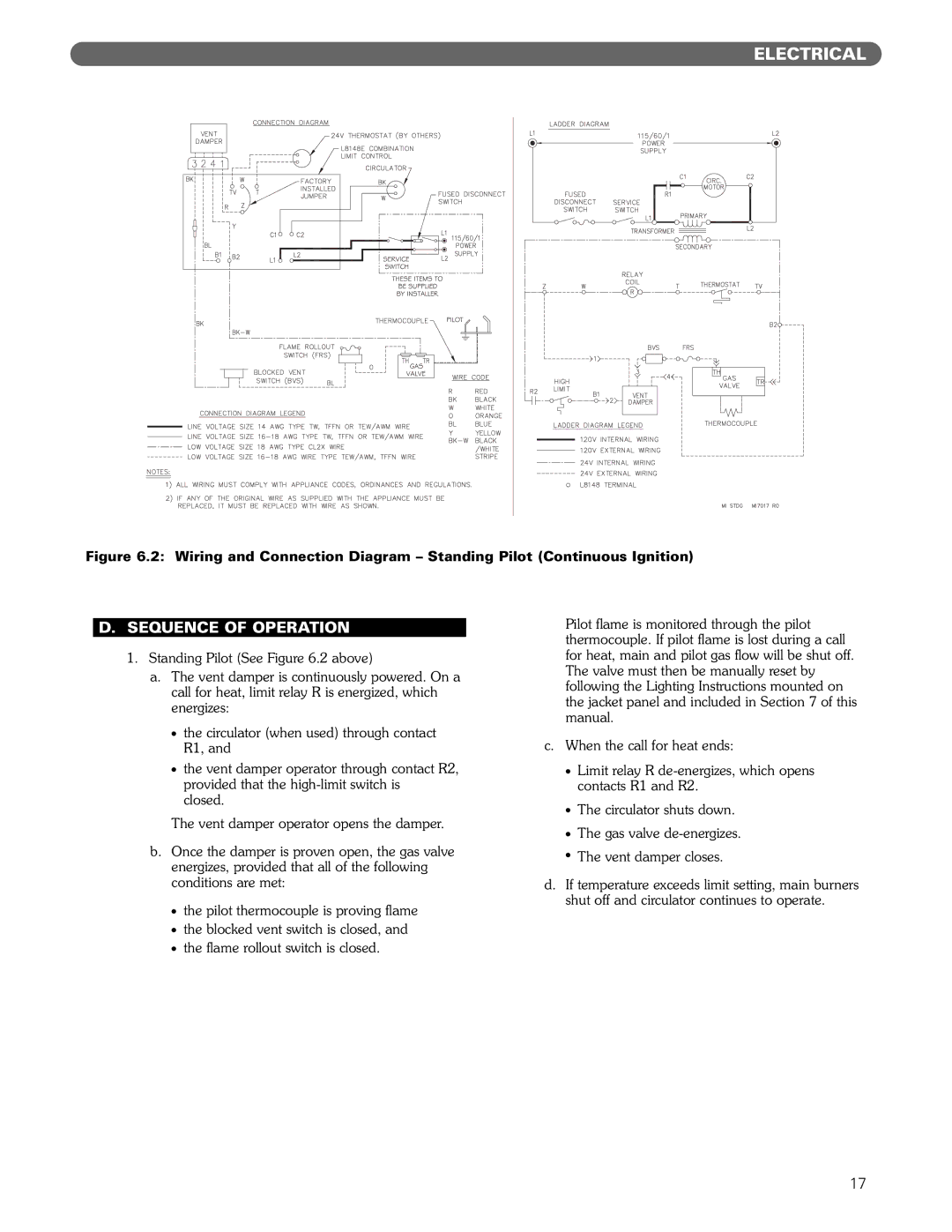
Figure 6.2: Wiring and Connection Diagram – Standing Pilot (Continuous Ignition)
D.SEQUENCE OF OPERATION
1.Standing Pilot (See Figure 6.2 above)
a.The vent damper is continuously powered. On a call for heat, limit relay R is energized, which energizes:
●the circulator (when used) through contact R1, and
●the vent damper operator through contact R2, provided that the
The vent damper operator opens the damper.
b.Once the damper is proven open, the gas valve energizes, provided that all of the following conditions are met:
●the pilot thermocouple is proving flame
●the blocked vent switch is closed, and
●the flame rollout switch is closed.
Pilot flame is monitored through the pilot thermocouple. If pilot flame is lost during a call for heat, main and pilot gas flow will be shut off. The valve must then be manually reset by following the Lighting Instructions mounted on the jacket panel and included in Section 7 of this manual.
c.When the call for heat ends:
●Limit relay R
●The circulator shuts down.
●The gas valve
●The vent damper closes.
d.If temperature exceeds limit setting, main burners shut off and circulator continues to operate.
17