Rear Panel
REAR PANEL DESCRIPTION
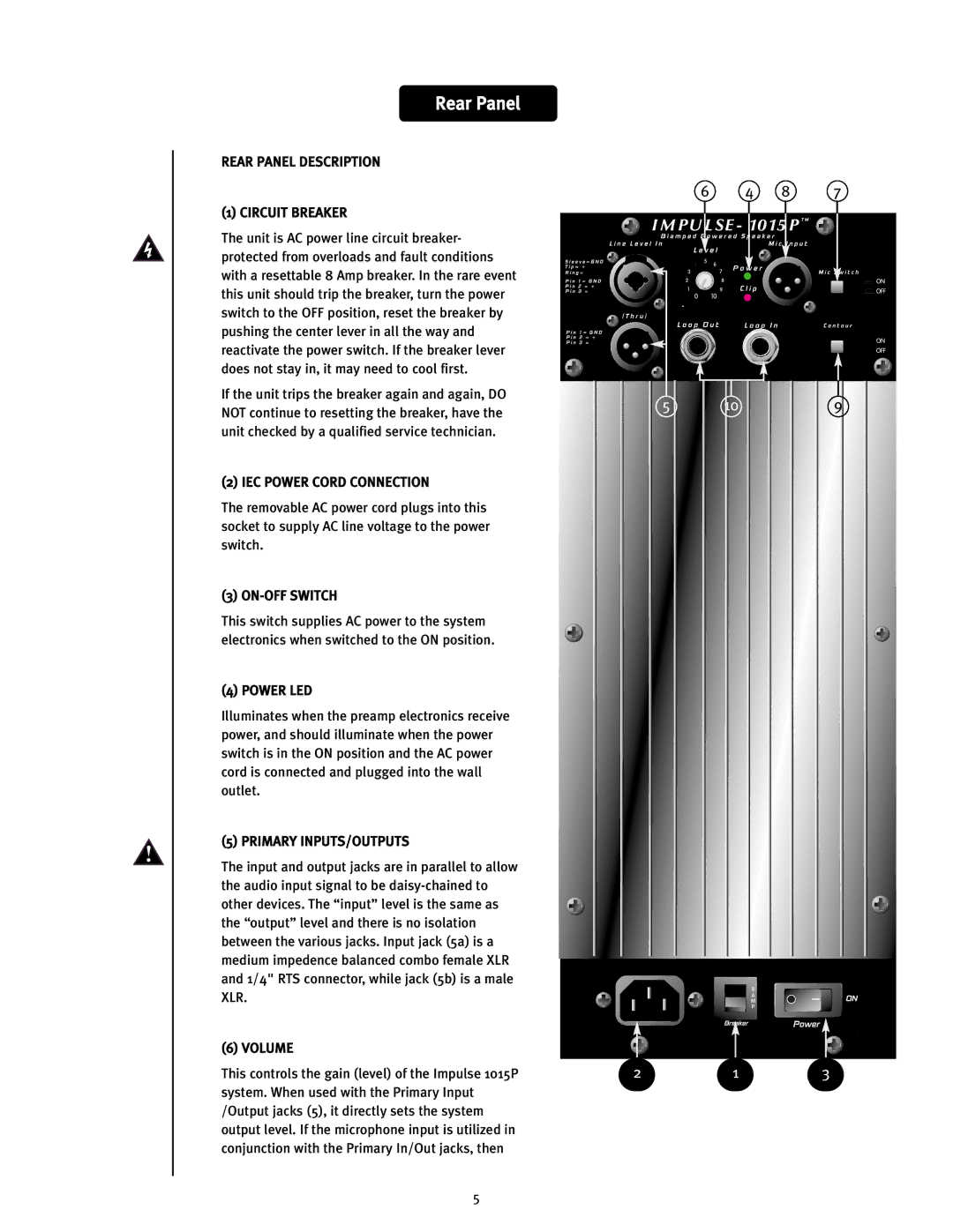
(1) CIRCUIT BREAKER
The unit is AC power line circuit breaker- protected from overloads and fault conditions with a resettable 8 Amp breaker. In the rare event this unit should trip the breaker, turn the power switch to the OFF position, reset the breaker by pushing the center lever in all the way and reactivate the power switch. If the breaker lever does not stay in, it may need to cool first.
If the unit trips the breaker again and again, DO NOT continue to resetting the breaker, have the unit checked by a qualified service technician.
(2) IEC POWER CORD CONNECTION
The removable AC power cord plugs into this socket to supply AC line voltage to the power switch.
(3) ON-OFF SWITCH
This switch supplies AC power to the system electronics when switched to the ON position.
(4) POWER LED
Illuminates when the preamp electronics receive power, and should illuminate when the power switch is in the ON position and the AC power cord is connected and plugged into the wall outlet.
(5) PRIMARY INPUTS/OUTPUTS
The input and output jacks are in parallel to allow the audio input signal to be
(6) VOLUME
This controls the gain (level) of the Impulse 1015P system. When used with the Primary Input /Output jacks (5), it directly sets the system output level. If the microphone input is utilized in conjunction with the Primary In/Out jacks, then
6 | 4 | 8 | 7 |
5 | 10 | 9 |
213
5