20
24 | 25 | 26 | 27 |
29
19
22
21
23
28
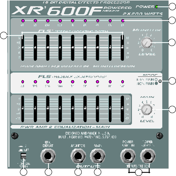
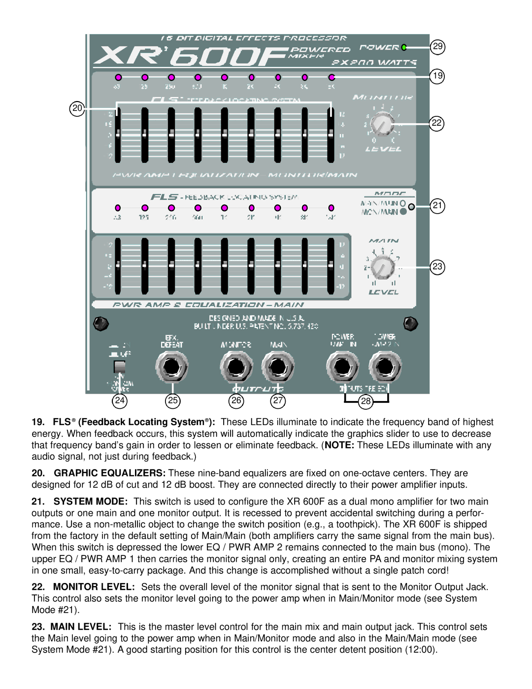
19.FLS ® (Feedback Locating System® ): These LEDs illuminate to indicate the frequency band of highest energy. When feedback occurs, this system will automatically indicate the graphics slider to use to decrease that frequency band’s gain in order to lessen or eliminate feedback. (NOTE: These LEDs illuminate with any audio signal, not just during feedback.)
20.GRAPHIC EQUALIZERS: These
21.SYSTEM MODE: This switch is used to configure the XR 600F as a dual mono amplifier for two main outputs or one main and one monitor output. It is recessed to prevent accidental switching during a perfor- mance. Use a
22.MONITOR LEVEL: Sets the overall level of the monitor signal that is sent to the Monitor Output Jack. This control also sets the monitor level going to the power amp when in Main/Monitor mode (see System Mode #21).
23.MAIN LEVEL: This is the master level control for the main mix and main output jack. This control sets the Main level going to the power amp when in Main/Monitor mode and also in the Main/Main mode (see System Mode #21). A good starting position for this control is the center detent position (12:00).
