| NOTE: Channels | 6 | low |
| 7 STEREO | ||
| channels. Only those features are mentioned below. For information on | cut |
| ||||
| features not mentioned please refer to the section for Channels |
| 5 |
| 5 |
| 11 |
|
|
|
|
|
|
| |
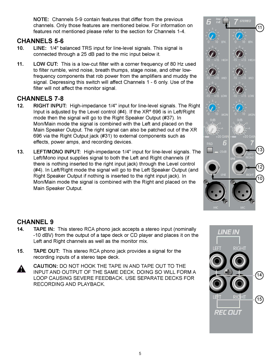
CHANNELS | 0 | 10 | EFX. | 0 | 10 | EFX. | |
10. | LINE: 1/4" balanced TRS input for |
| 0 |
| 0 |
|
|
|
|
|
|
|
| ||
| connected through a 25 dB pad to the mic input below it. |
|
|
|
|
|
|
11. | LOW CUT: This is a | +15 | HIGH | +15 | HIGH | ||
| 0 |
| 0 |
|
| ||
| to filter rumble, wind noise, breath thumps, stage noise, and other low- |
|
|
|
|
|
|
| frequency components that rob power from the amplifiers and muddy the | +15 | MID | +15 | MID | ||
| signal. Depressing this switch will affect Channels 1 - 6 only. Use of the | ||||||
|
| 0 |
| 0 |
|
| |
| filter will not affect the monitor signal. |
|
|
|
|
|
|
CHANNELS | +15 | LOW | +15 | LOW | |||
| 5 |
| 5 |
|
| ||
12. | RIGHT INPUT: |
|
|
|
|
|
|
| Input is adjusted by the Level control (#4). If the XR® 696 is in Left/Right | 0 | 10 | MON | 0 | 10 | MON |
| mode then the signal will go to the Right Speaker Output (#37). In | ||||||
| 0dB |
| 0dB |
| |||
| Mon/Main mode the signal is combined with the Left and placed on the |
|
| ||||
| +3 |
| +3 | ||||
| Main Speaker Output. The right signal can also be patched out of the XR | +6 |
| +6 | |||
|
|
|
| ||||
| 696 via the Right Output jack (#31) to external components such as |
| +20 GAIN |
| +20 GAIN | ||
| effects, power amps, and recording devices. | PAD | 6 |
|
| 7 | |
13. | LEFT/MONO INPUT: |
|
|
| 13 | ||
|
|
| LEFT/ | ||||
| Left/Mono input supplies signal to both the Left and Right channels (if |
|
|
|
|
| |
|
|
|
| LINE | MONO | ||
| there is nothing inserted to the right input jack) through the Level control |
|
|
|
|
| 12 |
| (#4). In Left/Right mode the signal will go to the Left Speaker Output (and |
|
|
|
|
| |
|
|
|
|
|
|
| |
| Right Speaker Output if nothing is inserted to the right input jack). In |
|
| LINE |
|
| RIGHT |
| Mon/Main mode the signal is combined with the Right and placed on the |
|
|
|
|
| 10 |
|
|
|
|
|
|
| |
| Main Speaker Output. |
|
|
|
|
|
|
|
|
| MIC |
|
| MIC |
|
CHANNEL 9
14.TAPE IN: This stereo RCA phono jack accepts a stereo input (nominally
15.TAPE OUT: This stereo RCA phono jack provides a signal for the recording inputs of a stereo tape deck.
CAUTION: DO NOT HOOK THE TAPE IN AND TAPE OUT TO THE INPUT AND OUTPUT OF THE SAME DECK. DOING SO WILL FORM A LOOP CAUSING SEVERE FEEDBACK. USE SEPARATE DECKS FOR RECORDING AND PLAYBACK.
LINE IN
LEFT RIGHT
14
LEFT RIGHT 15
REC OUT
5