![]() WARNING
WARNING
• If you are uncertain that product is properly installed, call customer care.
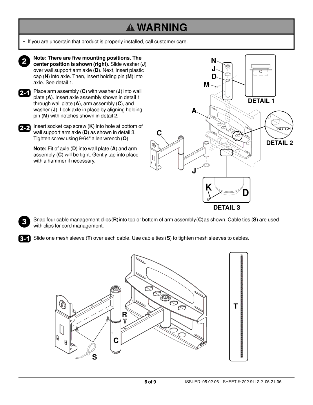
2 | Note: There are five mounting positions. The |
center position is shown (right). Slide washer (J) |
over wall support arm axle (D). Next, insert plastic cap (N) into axle. Then, insert holding pin (M) into axle. See detail 1.
N
J
D
M![]()
Place arm assembly (C) with washer (J) into wall |
| |
plate (A). Insert axle assembly shown in detail 1 | DETAIL 1 | |
through wall plate (A), arm assembly (C), and | ||
| ||
washer (J). Lock axle in place by aligning holding | A | |
pin (M) with notches shown in detail 2. |
| |
Insert socket cap screw (K) into hole at bottom of | NOTCH | |
| ||
wall support arm axle (D) as shown in detail 3. | C | |
Tighten screw using 9/64" allen wrench (Q). |
|
DETAIL 2
Note: Fit of axle (D) into wall plate (A) and arm assembly (C) will be tight. Gently tap into place with a hammer if necessary.
| J |
|
| K | D |
|
| |
|
| DETAIL 3 |
3 | Snap four cable management clips(R)into top or bottom of arm assembly(C)as shown. Cable ties (S) are used | |
| with clips for cord management. |
|
T
R
C
S
6 of 9 | ISSUED: |
