FX82052 REAR PANEL, -4 MODELS
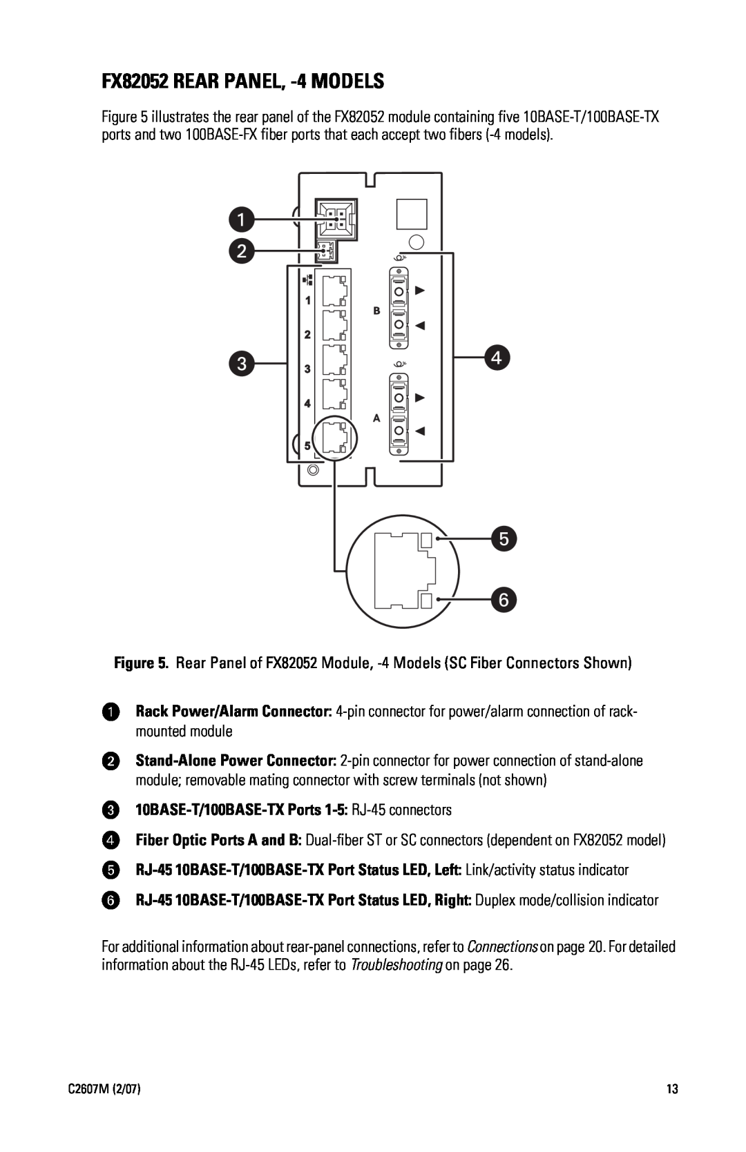
Figure 5 illustrates the rear panel of the FX82052 module containing five 10BASE-T/100BASE-TX ports and two 100BASE-FX fiber ports that each accept two fibers (-4 models).
Figure 5. Rear Panel of FX82052 Module, -4 Models (SC Fiber Connectors Shown)
ìRack Power/Alarm Connector: 4-pin connector for power/alarm connection of rack- mounted module
îStand-Alone Power Connector: 2-pin connector for power connection of stand-alone module; removable mating connector with screw terminals (not shown)
ï10BASE-T/100BASE-TX Ports 1-5: RJ-45 connectors
ñFiber Optic Ports A and B: Dual-fiber ST or SC connectors (dependent on FX82052 model)
óRJ-45 10BASE-T/100BASE-TX Port Status LED, Left: Link/activity status indicator
rRJ-45 10BASE-T/100BASE-TX Port Status LED, Right: Duplex mode/collision indicator
For additional information about rear-panel connections, refer to Connections on page 20. For detailed information about the RJ-45 LEDs, refer to Troubleshooting on page 26.