IN-CEILING INSTALLATION: FIXED CEILING/WALL
Refer to Figure 6 and complete the following steps.
1.Cut a
2.Remove the surface mount ring from the back box. Refer to Figure 5 and complete the following steps:
a.Place your fingers on the circular marks located on the sides of the surface mount ring.
b.Pinch the sides.
c.Lift and remove the surface mount ring from the back box.
3.Connect the video cable/wires.
BNC: Connect the BNC connector from the Camclosure to a mating BNC connector.
Twisted pair: Connect the blue wire to Video +; connect the gray wire to Video
4.Connect the power wires.
Table C. Power Input: Fixed Ceiling/Wall Installation
Voltage | Red Wire | Black Wire |
|
|
|
12 VDC | + | Ground |
|
|
|
24 VAC | ~ | ~ |
|
|
|
AC Operation Only: If you are wiring more than one ICS090 Camclosure to the same transformer, connect one side of the transformer to the red wire on all units, and then connect the other side of the transformer to the black wire on all units. Failure to connect all of the units in the same way will cause the cameras to be out of phase with each other, which might produce a vertical roll when switching between cameras.
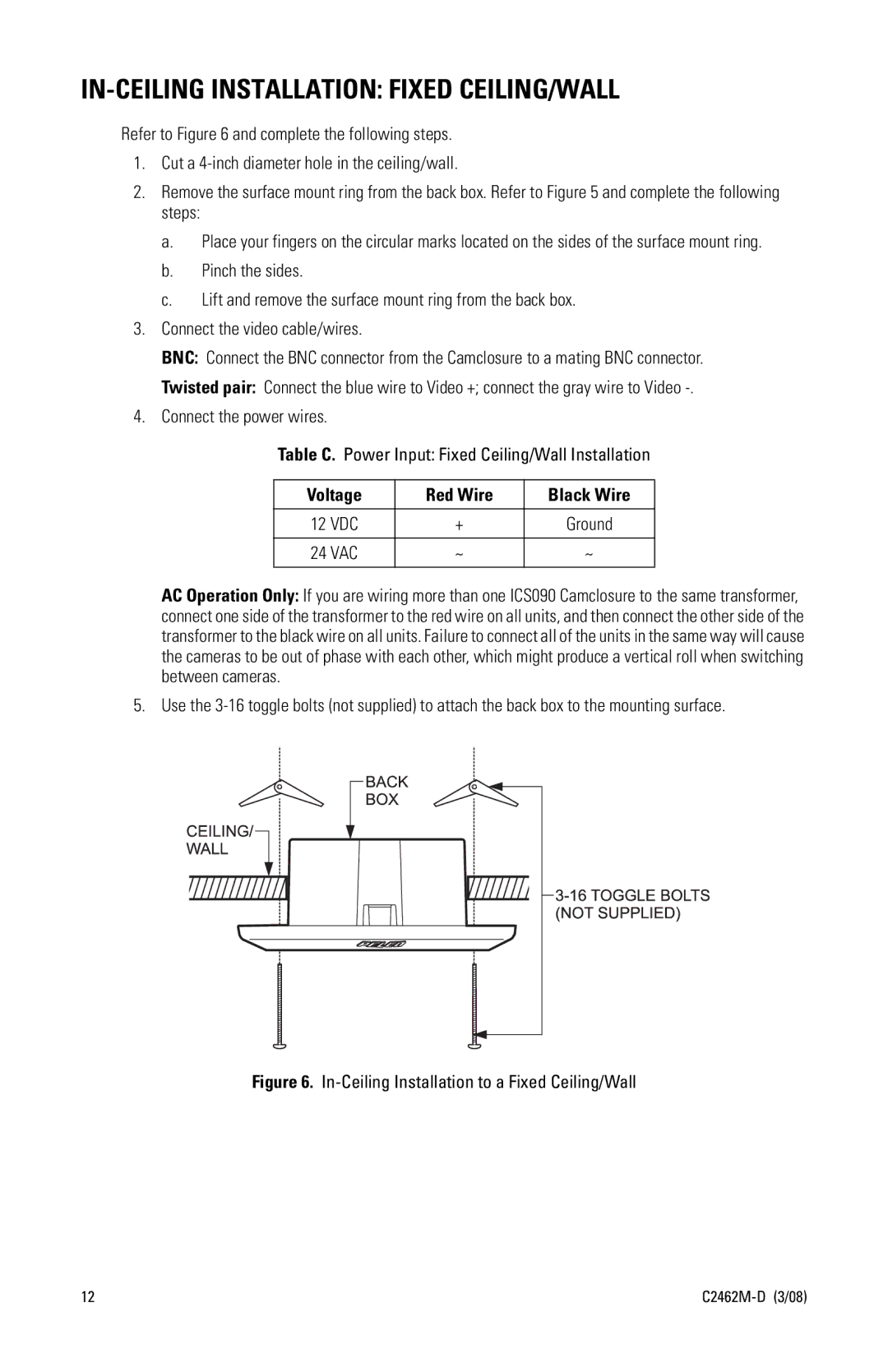
5. Use the
Figure 6. In-Ceiling Installation to a Fixed Ceiling/Wall
12 |