Manuals
/
Pelco
/
Photography
/
Security Camera
Pelco
BB5L Wiring Diagram for Spectra Ver. 3.0 and Spectra, Wiring Diagram for Spectra Lite
Models:
BB5L
1
10
20
20
Download
20 pages
39.63 Kb
7
8
9
10
11
12
13
14
<
>
Troubleshooting
Specs
Install
Warranty
Proceed to .2, WIRING
Page 10
Image 10
+5 to +24 VDC
EXTERNAL RELAY (WIRING EXAMPLE)
CONTROL
(RS-422)
7
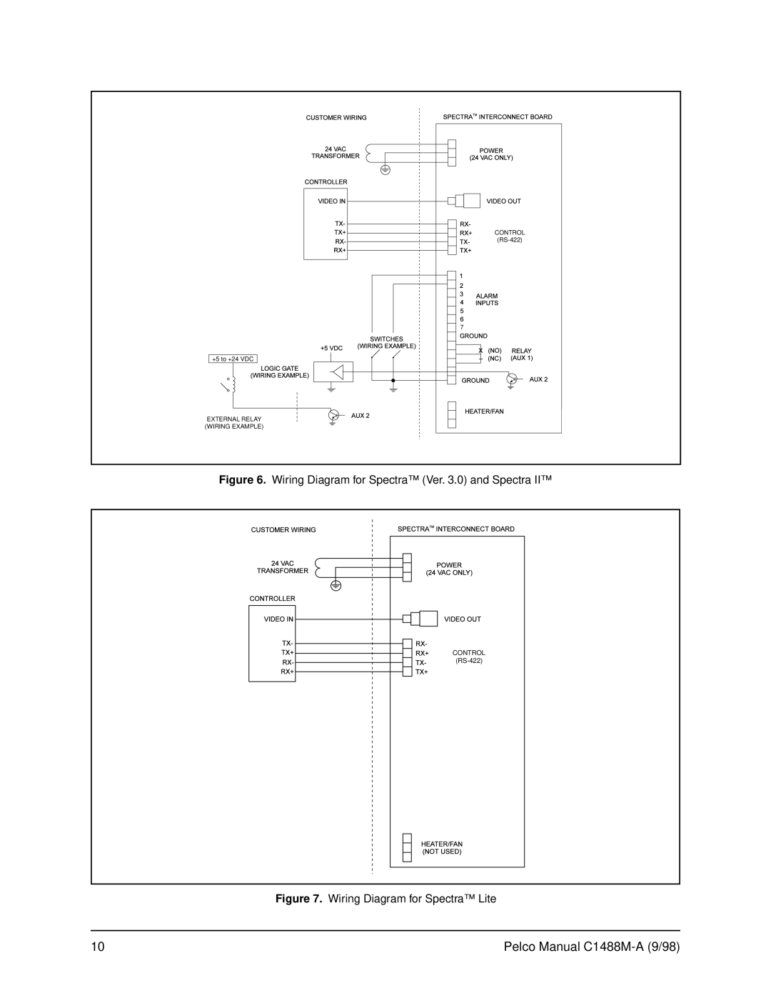
Figure 6.
Wiring Diagram for Spectra™ (Ver. 3.0) and Spectra II™
CONTROL
(RS-422)
Figure 7.
Wiring Diagram for Spectra™ Lite
10
Pelco Manual
C1488M-A
(9/98)
Page 9
Page 11
Page 10
Image 10
Page 9
Page 11
Contents
BB5A/BB5L Series Spectra Lite Spectra Software Version and
Spectra II Domes Back Box Installation Operation Manual C1488M-A 9/98
U L LISTED
LIST OF TABLES
CONTENTS
LIST OF ILLUSTRATIONS
REVISION HISTORY
1.0 GENERAL
1.1 IMPORTANT SAFEGUARDS AND WARNINGS
in this manual prior to installation and operation
The product and/or manual may bear the following marks
Increase the separation between the equipment and the receiver
1.2 REGULATORY NOTICES
Reorient or relocate the receiving antenna
Consult the dealer or an experienced radio/TV technician for help
Figure 1. Back Box Parts
1.3 UNPACKING INSTRUCTIONS
1.4 RECOMMENDED TOOLS
IN-CEILING MODELS
2.2 CERTIFICATIONS
2.0 DESCRIPTION
2.1 MODELS
Agency Compliance Certification
Figure 3. Conduit Fitting Installation
3.0 INSTALLATION FOR IN-CEILING MODELS
3.1 CEILING AND BACK BOX PREPARATION 3.1.1 Hard Ceiling
Proceed to Section 3.2, WIRING
Table A. Video Coaxial Cable Wiring Distances
3.2 WIRING
3.1.2 Suspended Ceiling
Proceed to Section 3.2, WIRING
HARD CEILING OR CEILING TILE
Figure 4. Installing Back Box
Figure 5. Fastening Back Box
+5 to +24 VDC EXTERNAL RELAY WIRING EXAMPLE
Figure 6. Wiring Diagram for Spectra Ver. 3.0 and Spectra
Figure 7. Wiring Diagram for Spectra Lite
CONTROL RS-422
Table B. 24 VAC Wiring Distances
Wire Gauge
Figure 8. Interconnect Door
3.3 BACK BOX INSTALLATION
Proceed to Section 3.4, BACK BOX CONNECTIONS
Figure 9. Transformer Wiring
3.4 BACK BOX CONNECTIONS
DOME 1 POWER DOME 2 POWER DOME 3 POWER
Figure 11. Interconnect Circuit Board for Spectra Lite
To 4-Wire terminal on circuit board
From controller
4.1 PENDANT-MOUNT INSTALLATION
4.0 INSTALLATION FOR PENDANT MODELS
4.2 SURFACE-MOUNT INSTALLATION
5.0 TROUBLESHOOTING
Symptom LED does not light
MECHANICAL
6.0 SPECIFICATIONS
Design and product specifications subject to change without notice
ELECTRICAL
Pendant Dome
Figure 12. SD5 Series Dimension Drawing
In-Ceiling Dome
NOTE VALUES IN PARENTHESES ARE CENTIMETERS, ALL OTHERS ARE INCHES
Pelco Manual C1488M-A 9/98
WARRANTY
7.0 WARRANTY AND RETURN INFORMATION
RETURNS