MOUNTING THE TRANSMITTER/RECEIVER
The FT8332 transmitter/FR8332 receiver can be mounted into a rack (refer to Mounting the Transmitter/Receiver into a Rack) or can be used as a
MOUNTING THE TRANSMITTER/RECEIVER INTO A RACK
The FT8332 transmitter/FR8332 receiver can mount into an
•
•Rack column depth: 24 to 30 inches (61 to 76 cm)
•
•Door systems are acceptable. Front doors must have at least 2 inches (5.1 cm) between the front bezel of the transmitter/receiver and the inside of the door. Rear doors may only be used on rack columns that are more than 26 inches (66 cm) deep
The transmitter/receiver occupies one rack unit (1.75 inches or 4.5 cm) of vertical rack space.
![]() WARNINGS:
WARNINGS:
•Secure the front and rear screws to the support rails.
•Make sure that the FT8332 transmitter/FR8332 receiver is level.
•Slots and openings in the cabinet provide ventilation to prevent the unit from overheating. Do not block those openings. Never place the unit near or over a radiator or heat register. When placing the unit in a rack, be sure to provide proper ventilation. Allow at least one rack unit (1.75 inches or 4.44 cm) of spacing between units.
To install the transmitter/receiver into a rack, do the following:
NOTE: The hardware necessary to mount the transmitter/receiver into a rack is supplied with the unit (refer to Figure 7).
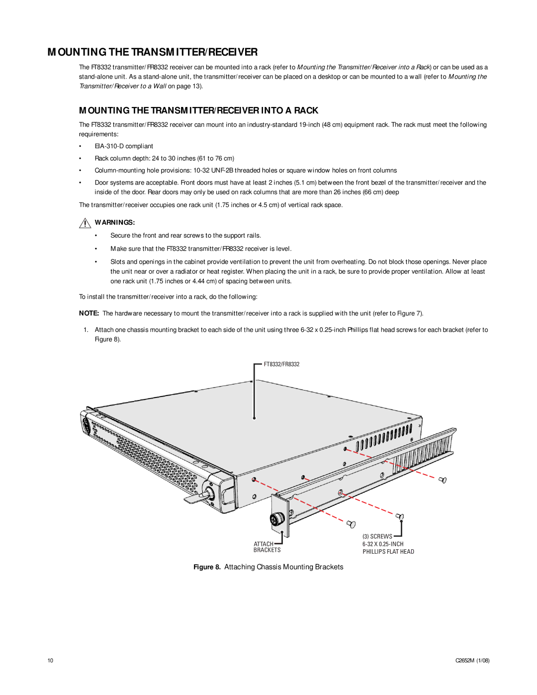
1.Attach one chassis mounting bracket to each side of the unit using three
FT8332/FR8332
| (3) SCREWS |
ATTACH | |
BRACKETS | PHILLIPS FLAT HEAD |
Figure 8. Attaching Chassis Mounting Brackets
10 | C2652M (1/08) |