CONNECTIONS
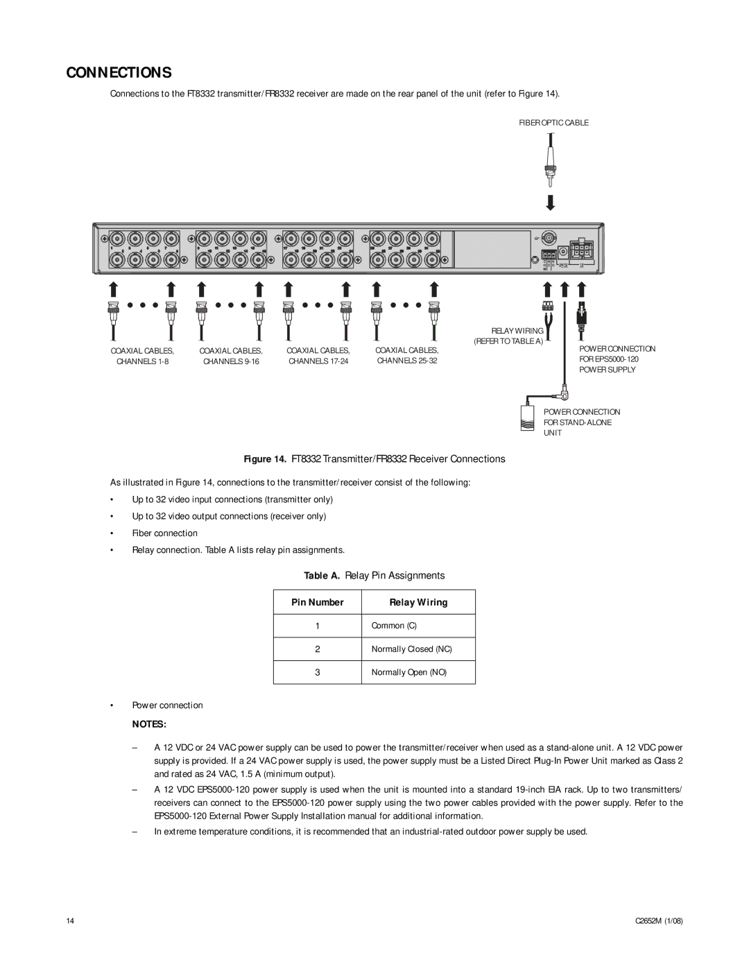
Connections to the FT8332 transmitter/FR8332 receiver are made on the rear panel of the unit (refer to Figure 14).
FIBER OPTIC CABLE
|
|
|
|
|
|
|
|
|
|
|
|
|
|
|
| RELAY WIRING |
|
|
|
|
| |||
|
|
|
|
|
|
|
|
|
|
|
|
|
|
|
|
|
|
|
|
| ||||
|
|
|
|
|
|
|
|
|
|
|
|
|
|
|
|
|
|
|
|
| ||||
COAXIAL CABLES, | COAXIAL CABLES, | COAXIAL CABLES, |
| COAXIAL CABLES, | (REFER TO TABLE A) |
|
|
| POWER CONNECTION | |||||||||||||||
|
|
|
|
|
|
|
| |||||||||||||||||
CHANNELS | CHANNELS | CHANNELS |
| CHANNELS |
|
|
|
|
|
|
| FOR | ||||||||||||
|
|
|
|
|
|
|
|
|
|
|
|
|
|
|
|
|
|
|
|
|
|
| POWER SUPPLY | |
|
|
|
|
|
|
|
|
|
|
|
|
|
|
|
|
|
|
|
|
|
|
|
|
|
|
|
|
|
|
|
|
|
|
|
|
|
|
|
|
|
|
|
|
|
|
|
|
|
|
|
|
|
|
|
|
|
|
|
|
|
|
|
|
|
|
|
|
|
|
|
|
|
|
|
|
|
|
|
|
|
|
|
|
|
|
|
|
|
|
|
|
|
|
|
|
|
|
|
|
POWER CONNECTION
FOR
UNIT
Figure 14. FT8332 Transmitter/FR8332 Receiver Connections
As illustrated in Figure 14, connections to the transmitter/receiver consist of the following:
•Up to 32 video input connections (transmitter only)
•Up to 32 video output connections (receiver only)
•Fiber connection
•Relay connection. Table A lists relay pin assignments.
Table A. Relay Pin Assignments
Pin Number | Relay Wiring |
1Common (C)
2Normally Closed (NC)
3Normally Open (NO)
•Power connection
NOTES:
–A 12 VDC or 24 VAC power supply can be used to power the transmitter/receiver when used as a
–A 12 VDC
–In extreme temperature conditions, it is recommended that an
14 | C2652M (1/08) |