Installation
PACKAGE CONTENTS
The following items are supplied:
1FT8332 transmitter or FR8332 receiver
1Accessory pack:
1 Screw terminal,
1 Regulated switching power supply,
2Front bezel keys
1Rack mount kit (included with accessory pack):
2Chassis mounting brackets with thumbscrews
6 Screws,
2 Adjustable support rail sets (each set includes one
4 Screws,
4 Screws,
10 Cage nuts,
1 FT8332/FR8332 Fiber Transmitter and Receiver Installation manual
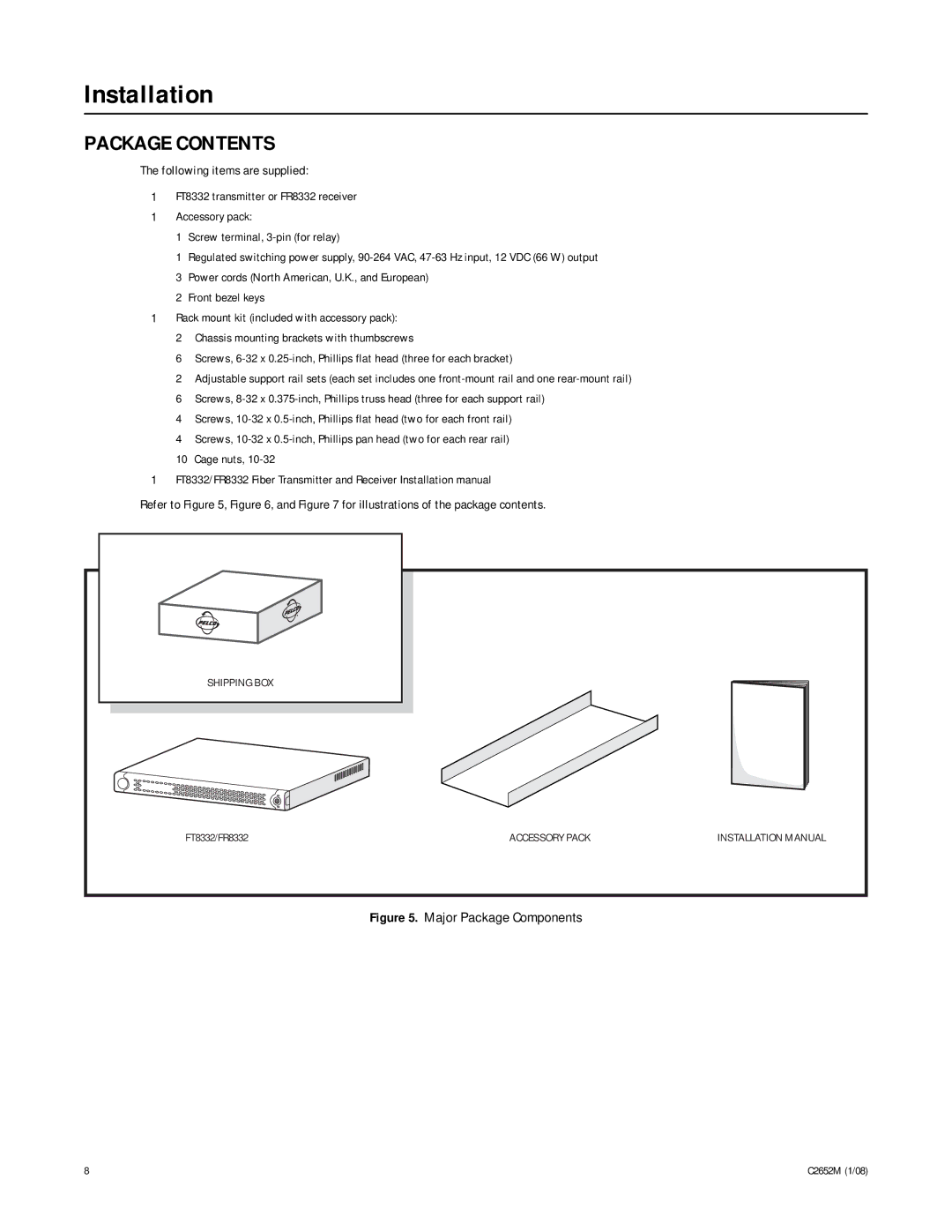
Refer to Figure 5, Figure 6, and Figure 7 for illustrations of the package contents.
SHIPPING BOX |
|
|
FT8332/FR8332 | ACCESSORY PACK | INSTALLATION MANUAL |
Figure 5. Major Package Components
8 | C2652M (1/08) |