REAR PANEL
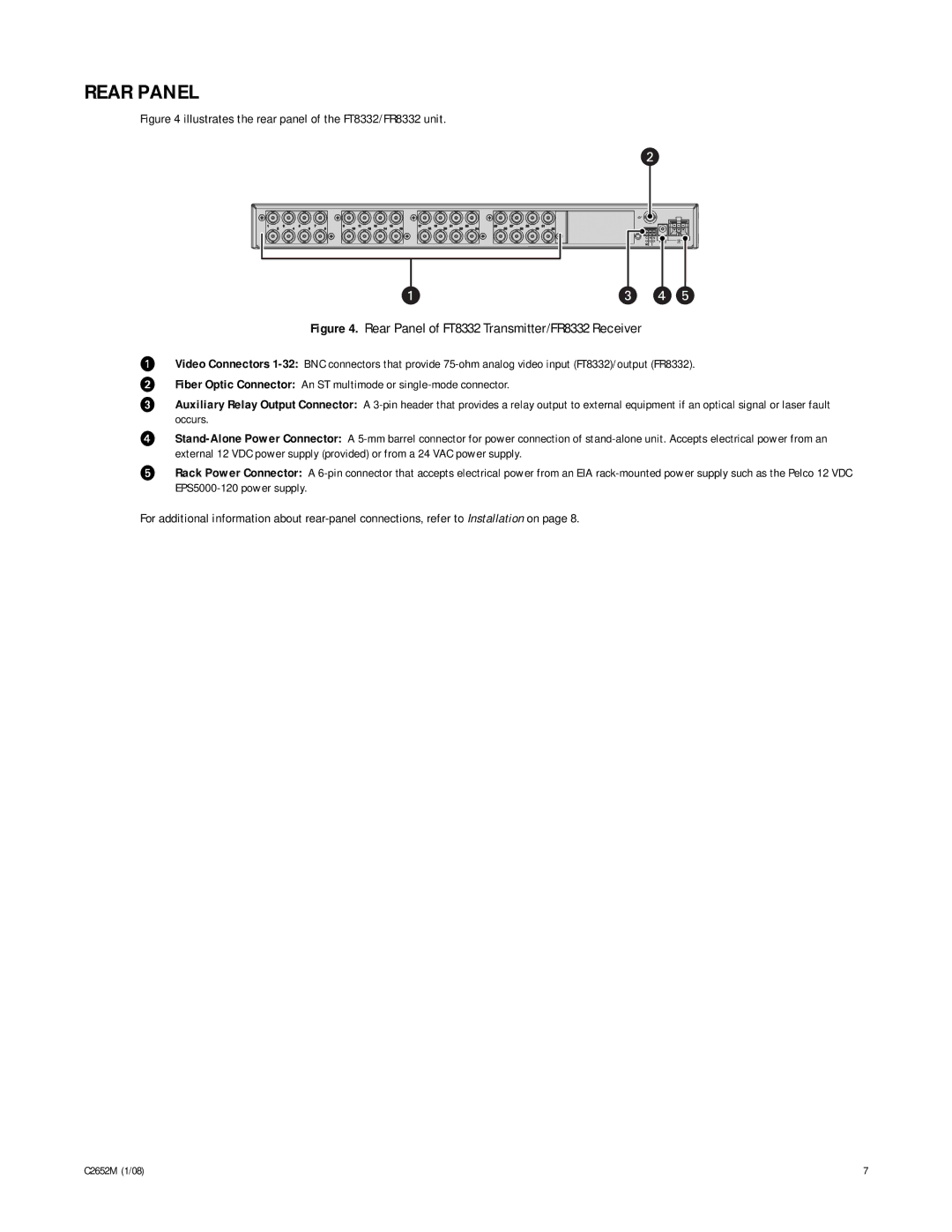
Figure 4 illustrates the rear panel of the FT8332/FR8332 unit.
Figure 4. Rear Panel of FT8332 Transmitter/FR8332 Receiver
ìVideo Connectors 1-32:BNC connectors that provide 75-ohm analog video input (FT8332)/output (FR8332).
îFiber Optic Connector: An ST multimode or single-mode connector.
ïAuxiliary Relay Output Connector: A 3-pin header that provides a relay output to external equipment if an optical signal or laser fault occurs.
ñStand-Alone Power Connector: A 5-mm barrel connector for power connection of stand-alone unit. Accepts electrical power from an external 12 VDC power supply (provided) or from a 24 VAC power supply.
óRack Power Connector: A 6-pin connector that accepts electrical power from an EIA rack-mounted power supply such as the Pelco 12 VDC EPS5000-120 power supply.
For additional information about rear-panel connections, refer to Installation on page 8.