FRONT PANEL
The front panel of the FT8332/FR8332 unit provides a removable bezel. Figure 2 illustrates the front of the unit with the bezel attached. Figure 3 illustrates the front of the unit with the bezel removed.
NOTE: The Contact Closure Activation and Data Activity LEDs shown in Figure 3 are not used.
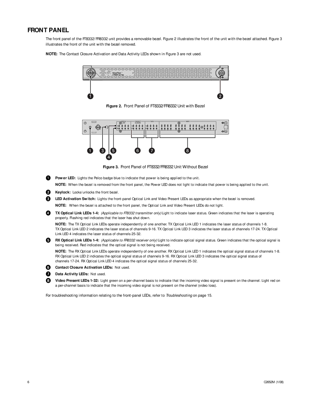
Figure 2. Front Panel of FT8332/FR8332 Unit with Bezel
Figure 3. Front Panel of FT8332/FR8332 Unit Without Bezel
ìPower LED: Lights the Pelco badge blue to indicate that power is being applied to the unit.
NOTE: When the bezel is removed from the front panel, the Power LED does not light to indicate that power is being applied to the unit.
îKeylock: Locks/unlocks the front bezel.
ïLED Activation Switch: Lights the
NOTE: When the bezel is attached to the front panel, the Optical Link and Video Present LEDs do not light.
ñTX Optical Link LEDs
NOTE: The TX Optical Link LEDs operate independently of one another. TX Optical Link LED 1 indicates the laser status of channels
TX Optical Link LED 2 indicates the laser status of channels
óRX Optical Link LEDs
NOTE: The RX Optical Link LEDs operate independently of one another. RX Optical Link LED 1 indicates the optical signal status of channels
rContact Closure Activation LEDs: Not used.
sData Activity LEDs: Not used.
tVideo Present LEDs
For troubleshooting information relating to the
6 | C2652M (1/08) |