Basic Operation continued
Indicator Lights (Front Panel)
Basic Operation continued
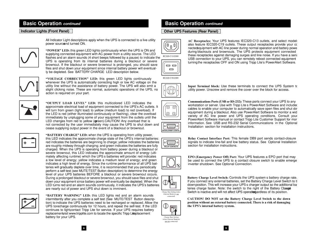
Other UPS Features (Rear Panel)
All Indicator Light descriptions apply when the UPS is connected to a live utility power source and turned ON.
“POWER” LED: this green LED lights continuously when the UPS is ON and supplying connected equipment with AC power from a utility source. The LED flashes and an alarm sounds (4 short beeps followed by a pause) to indicate the UPS is operating from its internal batteries during a blackout or severe brownout. If the blackout or severe brownout is prolonged, you should save files and shut down your equipment since internal battery power will eventual- ly be depleted. See “BATTERY CHARGE” LED description below.
AC Receptacles: Your UPS features
“VOLTAGE CORRECTION” LED: this green LED lights continuously whenever the UPS is automatically correcting high or low AC voltage on the
utility line without the assistance of battery power. The UPS will also emit a slight clicking noise. These are normal, automatic operations of the UPS, no action is required on your part.
“OUTPUT LOAD LEVEL” LED: this multicolored LED indicates the approximate electrical load of equipment connected to the UPS's AC outlets. It will turn from green (light load) to yellow (medium load) to red (overload). If the LED is red (either illuminated continuously or flashing), clear the overload immediately by unplugging some of your equipment from the outlets until the LED changes from red to yellow (or green). CAUTION! Any overload that is not corrected by the user immediately may cause the UPS to shut down and cease supplying output power in the event of a blackout or brownout.
“BATTERY CHARGE” LED: when the UPS is operating from utility power, this LED indicates the approximate charge state of the UPS's internal batteries: red indicates the batteries are beginning to charge; yellow indicates the batteries are roughly midway through charging; and green indicates the batteries are fully charged. When the UPS is operating from battery power during a blackout or severe brownout, this LED indicates the approximate amount of energy (ulti- mately affecting runtime) which the UPS’s batteries will provide: red indicates a low level of energy; yellow indicates a medium level of energy; and green indicates a high level of energy. Since the runtime performance of all UPS bat- teries will gradually deplete over time, it is recommended that you periodically perform a
“BATTERY WARNING” LED: this LED lights red and an alarm sounds intermittently after you complete a self test (See “MUTE/TEST” Button descrip- tion) to indicate the UPS batteries need to be recharged or replaced. Allow the UPS to recharge continuously for 12 hours, and repeat the
8
Charge Rate Setting (when
External Batteries are
connected)
Charge Rate Setting
(when External Batteries
are not connected)
Input Terminal block: Use these terminals to connect the UPS System to utility power. Unscrew and remove the cover over the block for access.
Communications Ports (USB
Relay Contact Interface Port: This female DB9 port sends
EPO (Emergency Power Off) Port: Your UPS features a EPO port that may be used to connect the UPS to a contact closure switch to enable emergency inverter shutdown. See Optional Connection.
Battery Charge Level Switch: Controls the UPS system’s battery charge rate. If you connect any external batteries, set the Battery Charge Level Switch to the down position. This will increase your UPS’s charger output so the additional bat- teries charge faster. Note: the switch to the right of the Battery Charge Level Switch is inactive and will not affect UPS operation regardless of its position.
CAUTION! DO NOT set the Battery Charge Level Switch to the down position without an external battery connected. There is a risk of damaging the UPS’s internal battery system.
9