BLACK-WHITE OR DAY/NIGHT VIDEO SETTINGS
For the best picture quality, adjust the DIP switch settings. Refer to Figure 9 and Table E, and then complete the following steps:
1.Plug the power cord into a power source to turn on the unit. When the input video signal is present, the LED on the front panel glows orange. If the video range is incorrect, the LED glows red.
NOTE: The color burst
2.Unscrew the four thumb screws located on the front panel of the receiver.
3.Carefully open the front panel until the hinges are completely exposed. The front panel should remain attached to the receiver.
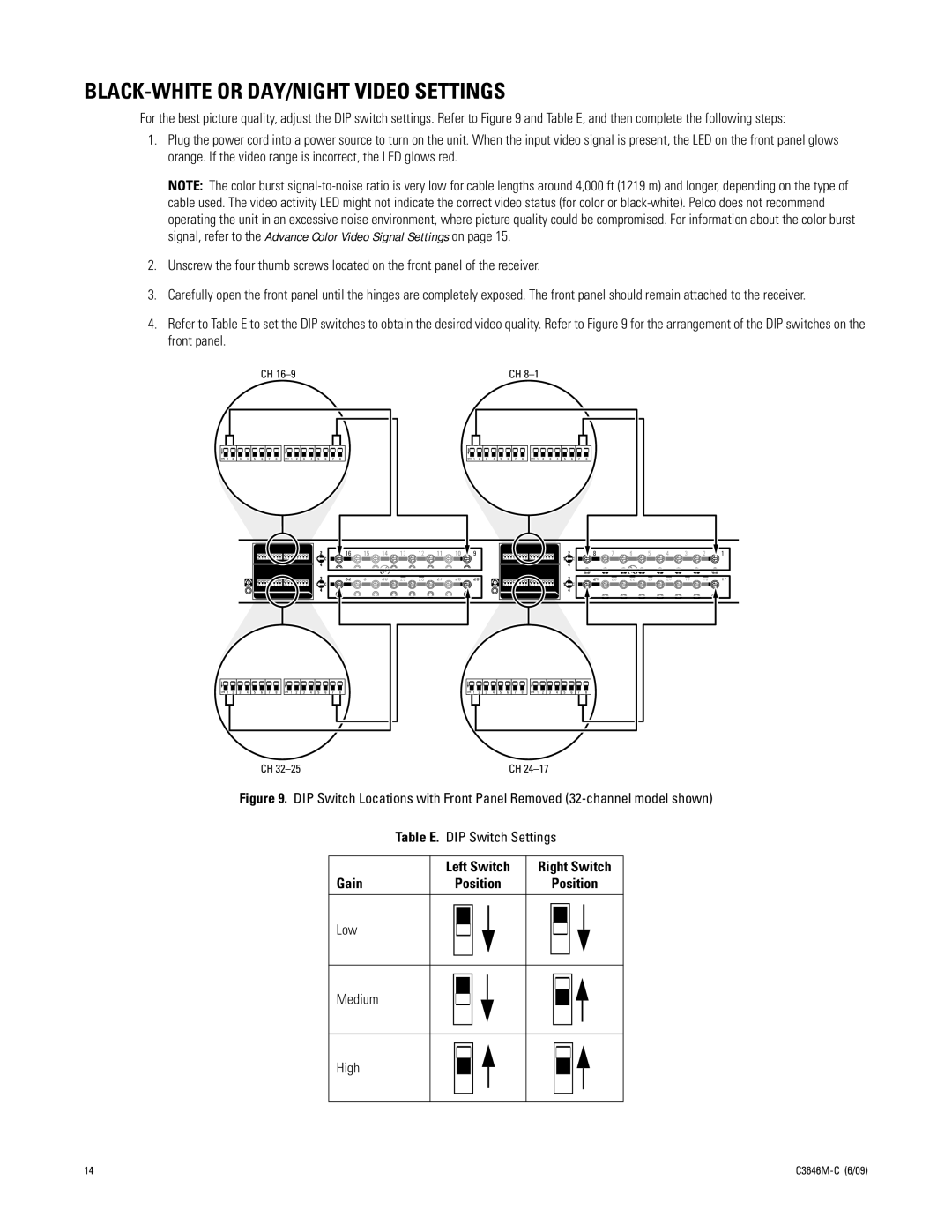
4.Refer to Table E to set the DIP switches to obtain the desired video quality. Refer to Figure 9 for the arrangement of the DIP switches on the front panel.
CH |
|
|
|
|
|
|
|
|
|
|
|
|
|
| CH |
| |||||||||||||||||||||||||
|
|
|
|
|
|
|
|
|
|
|
|
|
|
|
|
|
|
|
|
|
|
|
|
|
|
|
|
|
|
|
|
|
|
|
|
|
|
|
|
|
|
|
|
|
|
|
|
|
|
|
|
|
|
|
|
|
|
|
|
|
|
|
|
|
|
|
|
|
|
|
|
|
|
|
|
|
|
|
|
|
|
|
|
|
|
|
|
|
|
|
|
|
|
|
|
|
|
|
|
|
|
|
|
|
|
|
|
|
|
|
|
|
|
|
|
|
|
|
|
|
|
|
|
|
|
|
|
|
|
|
|
|
|
|
|
|
|
|
|
|
|
|
|
|
|
|
|
|
|
|
|
|
|
|
|
|
|
|
|
|
|
|
|
|
|
|
|
|
|
|
|
|
|
|
|
|
|
|
|
|
|
|
|
|
|
|
|
|
|
|
|
|
|
|
|
|
|
|
|
|
|
|
|
|
|
|
|
|
|
|
|
|
|
|
|
|
|
|
|
|
|
|
|
|
|
|
|
|
|
|
|
|
|
|
|
|
|
|
|
|
|
|
|
|
|
|
|
|
|
|
|
ON 1 2 3 4 5 6 7 8 | ON 1 2 3 4 5 6 7 8 | ON 1 2 3 4 5 6 7 8 | ON 1 2 3 4 5 6 7 8 |
|
|
|
| 16 | 15 | 14 | 11 | 10 |
| 9 |
|
|
|
| 8 | 1 | ||
|
|
|
| |||||||||||||||
|
|
|
|
|
|
|
|
|
|
|
|
|
|
|
|
| 24 | 17 |
|
|
|
|
|
|
|
|
|
|
|
|
|
|
|
|
| ||
|
|
|
| 32 | 31 |
|
|
|
|
|
| 25 |
|
|
|
| ||
1 |
|
|
| 30 | 27 | 26 | 2 |
|
|
| ||||||||
|
|
|
|
|
|
|
|
|
|
|
|
|
|
|
|
| ||
|
|
|
|
|
|
|
|
|
|
|
|
|
|
|
|
| ||
|
|
|
|
|
|
|
|
|
|
|
|
|
|
|
|
|
|
|
|
|
|
|
|
|
|
|
|
|
|
|
|
|
|
|
|
|
|
|
|
|
|
|
|
|
|
|
|
|
|
|
|
|
|
|
|
|
|
|
|
|
|
|
|
|
|
|
|
|
|
|
|
|
|
|
|
|
|
|
|
|
|
|
|
|
|
|
|
|
|
|
|
|
|
|
|
|
|
|
|
|
|
|
|
|
|
|
|
|
|
|
|
|
|
|
|
|
|
|
ON 1 2 | 3 4 | 5 6 | 7 8 | ON 1 2 | 3 4 | 5 6 | 7 8 |
|
| ON 1 2 | 3 4 | 5 6 | 7 8 | ON 1 2 | 3 4 | 5 6 | 7 8 |
|
| ||||||||||||||||||||||||||||||
|
|
|
|
|
|
|
|
|
|
|
|
|
|
|
|
|
|
|
|
|
|
|
|
|
|
|
|
|
|
|
|
|
|
|
|
|
|
|
|
|
|
|
|
|
|
|
|
|
|
|
|
|
|
|
|
|
|
|
|
|
|
|
|
|
|
|
|
|
|
|
|
|
|
|
|
|
|
|
|
|
|
|
|
|
|
|
|
|
|
|
|
|
|
|
|
|
|
|
|
|
|
|
|
|
|
|
|
|
|
|
|
|
|
|
|
|
|
|
|
|
|
|
|
|
|
|
|
|
|
|
|
|
|
|
|
|
|
|
|
|
|
|
|
|
|
|
|
|
|
|
|
|
|
|
|
|
|
|
|
|
|
|
|
|
|
|
|
|
|
|
|
|
|
|
|
|
|
|
|
|
|
|
|
|
|
|
|
|
|
|
|
|
|
|
|
|
|
|
|
CH | CH |
Figure 9. DIP Switch Locations with Front Panel Removed (32-channel model shown)
Table E. DIP Switch Settings
Gain
Left Switch
Position
Right Switch
Position
Low
Medium
High
14 |