Configuration
This section describes an optional advanced tuning procedure for troubleshooting a video path. For most installations, the steps detailed in Color Video Range Settings on page 13 should be sufficient to set up the unit.
Required Equipment
•Video signal generator
•Oscilloscope
NOTE: A signal generator and oscilloscope are preferred to perform this procedure, but a video signal from a camera observed on an oscilloscope can also be used for this process.
ADVANCE COLOR VIDEO SIGNAL SETTINGS
To check the color burst level and set the video signal for optimal output:
1.From a signal generator or a color camera, send a multiburst color video signal through the UTP to the unit.
2.Set the rotary switch to the correct position for the cable length (refer to Table D on page 13).
3.The LED for the camera input on the front panel glows green if video is present. If the color video range is incorrect, the LED glows orange or red. Turn the rotary switch on the front panel, beginning at position 1, clockwise until the LED glows green.
NOTE: If the LED glows green at more than one switch position, set the rotary switch at the lower position; this will ensure
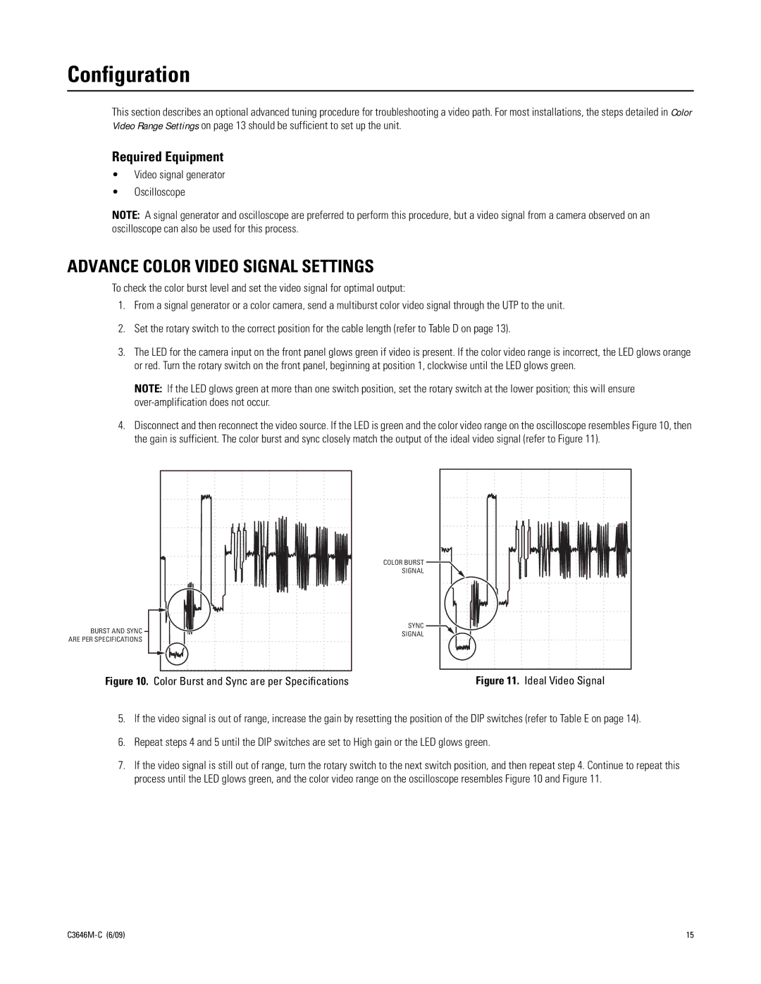
4.Disconnect and then reconnect the video source. If the LED is green and the color video range on the oscilloscope resembles Figure 10, then the gain is sufficient. The color burst and sync closely match the output of the ideal video signal (refer to Figure 11).
BURST AND SYNC
ARE PER SPECIFICATIONS
Figure 10. Color Burst and Sync are per Specifications
COLOR BURST |
SIGNAL |
SYNC |
SIGNAL |
Figure 11. Ideal Video Signal
5.If the video signal is out of range, increase the gain by resetting the position of the DIP switches (refer to Table E on page 14).
6.Repeat steps 4 and 5 until the DIP switches are set to High gain or the LED glows green.
7.If the video signal is still out of range, turn the rotary switch to the next switch position, and then repeat step 4. Continue to repeat this process until the LED glows green, and the color video range on the oscilloscope resembles Figure 10 and Figure 11.
15 |