FRONT PANEL
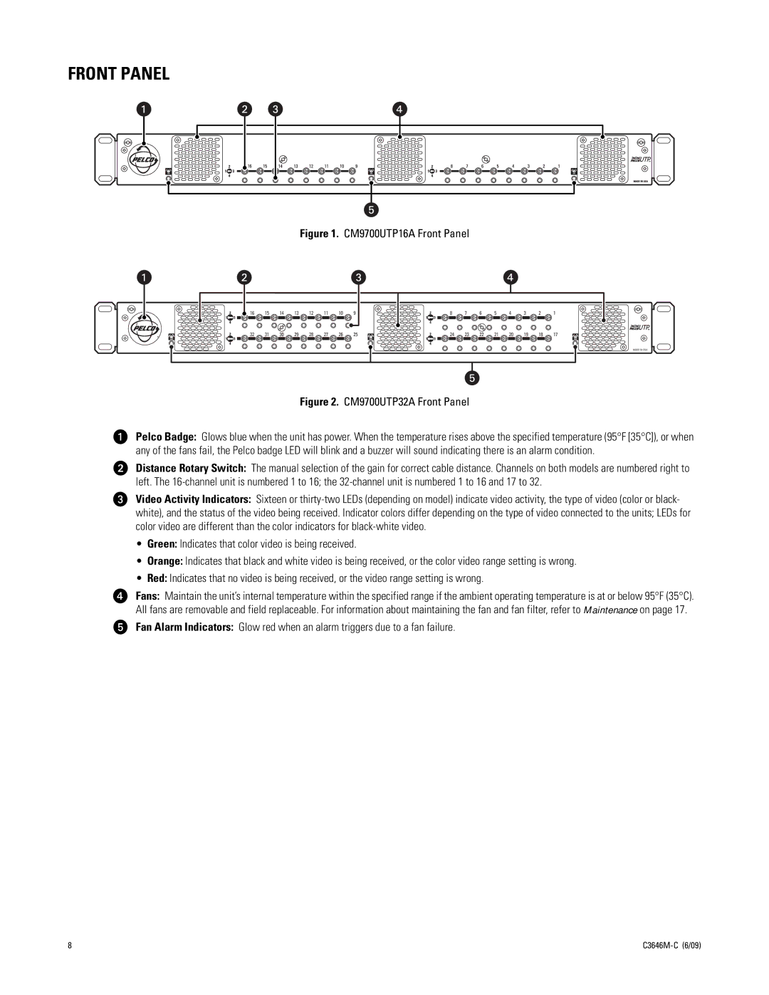
Figure 1. CM9700UTP16A Front Panel
| 16 | 15 | 14 | 13 | 12 | 11 | 10 | 9 |
|
1 | 32 | 31 | 30 | 29 | 28 | 27 | 26 | 25 | 2 |
8 | 7 | 6 | 5 | 4 | 3 | 2 | 1 |
|
24 | 23 | 22 | 21 | 20 | 19 | 18 | 17 | 3 |
MADE IN USA
Figure 2. CM9700UTP32A Front Panel
ìPelco Badge: Glows blue when the unit has power. When the temperature rises above the specified temperature (95°F [35°C]), or when any of the fans fail, the Pelco badge LED will blink and a buzzer will sound indicating there is an alarm condition.
îDistance Rotary Switch: The manual selection of the gain for correct cable distance. Channels on both models are numbered right to left. The
ïVideo Activity Indicators: Sixteen or
•Green: Indicates that color video is being received.
•Orange: Indicates that black and white video is being received, or the color video range setting is wrong.
•Red: Indicates that no video is being received, or the video range setting is wrong.
ñFans: Maintain the unit’s internal temperature within the specified range if the ambient operating temperature is at or below 95°F (35°C). All fans are removable and field replaceable. For information about maintaining the fan and fan filter, refer to Maintenance on page 17.
óFan Alarm Indicators: Glow red when an alarm triggers due to a fan failure.
8 |