BACK PANEL
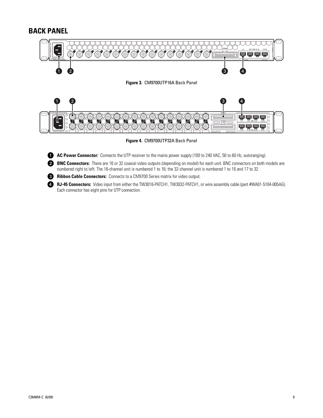
Figure 3. CM9700UTP16A Back Panel
1 17 | 2 18 | 3 19 | 4 20 | 5 21 | 6 22 | 7 23 | 8 24 | 9 25 | 10 26 | 11 27 | 12 28 | 13 29 | 14 30 | 15 31 | 16 32 | TO MXB | ||||
|
|
|
|
|
|
|
|
|
|
|
|
|
|
|
|
|
Figure 4. CM9700UTP32A Back Panel
ìAC Power Connector: Connects the UTP receiver to the mains power supply (100 to 240 VAC, 50 to 60 Hz, autoranging).
îBNC Connectors: There are 16 or 32 coaxial video outputs (depending on model) for each unit. BNC connectors on both models are numbered right to left. The
ïRibbon Cable Connectors: Connects to a CM9700 Series matrix for video output.
ñ
9 |