CONNECTING SERIAL PTZ
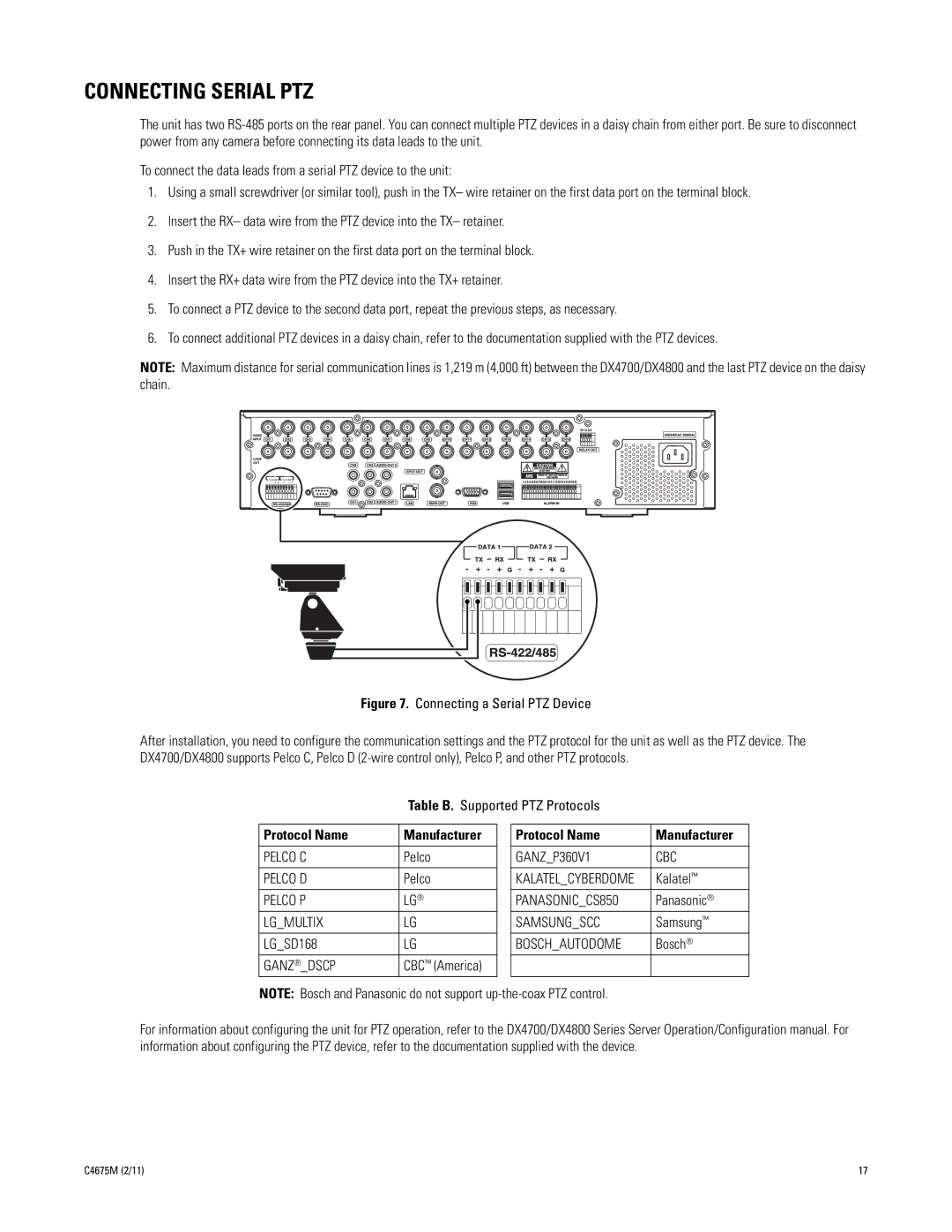
The unit has two
To connect the data leads from a serial PTZ device to the unit:
1.Using a small screwdriver (or similar tool), push in the TX– wire retainer on the first data port on the terminal block.
2.Insert the RX– data wire from the PTZ device into the TX– retainer.
3.Push in the TX+ wire retainer on the first data port on the terminal block.
4.Insert the RX+ data wire from the PTZ device into the TX+ retainer.
5.To connect a PTZ device to the second data port, repeat the previous steps, as necessary.
6.To connect additional PTZ devices in a daisy chain, refer to the documentation supplied with the PTZ devices.
NOTE: Maximum distance for serial communication lines is 1,219 m (4,000 ft) between the DX4700/DX4800 and the last PTZ device on the daisy chain.
Figure 7. Connecting a Serial PTZ Device
After installation, you need to configure the communication settings and the PTZ protocol for the unit as well as the PTZ device. The DX4700/DX4800 supports Pelco C, Pelco D
Table B. Supported PTZ Protocols
Protocol Name | Manufacturer |
|
|
PELCO C | Pelco |
|
|
PELCO D | Pelco |
|
|
PELCO P | LG® |
LG_MULTIX | LG |
|
|
LG_SD168 | LG |
|
|
GANZ®_DSCP | CBC™ (America) |
Protocol Name | Manufacturer |
|
|
GANZ_P360V1 | CBC |
|
|
KALATEL_CYBERDOME | Kalatel™ |
PANASONIC_CS850 | Panasonic® |
SAMSUNG_SCC | Samsung™ |
BOSCH_AUTODOME | Bosch® |
|
|
NOTE: Bosch and Panasonic do not support
For information about configuring the unit for PTZ operation, refer to the DX4700/DX4800 Series Server Operation/Configuration manual. For information about configuring the PTZ device, refer to the documentation supplied with the device.
C4675M (2/11) | 17 |
