
DX9100 specifications
The Pelco DX9100 is a versatile and robust digital video recorder (DVR) specifically designed for surveillance applications. Featuring innovative technologies and a user-friendly interface, the DX9100 provides an exceptional solution for security monitoring across various environments, including retail, commercial, and public spaces.One of the primary features of the DX9100 is its high-definition video recording capability. The DVR supports multiple video formats, allowing the integration of various camera systems. With up to 16 channels of real-time recording, the DX9100 ensures that every critical moment is captured with clarity, offering resolutions that can reach up to 4CIF. This flexibility makes it suitable for diverse monitoring needs, from small installations to large-scale systems.
Another noteworthy characteristic of the DX9100 is its advanced compression technologies. Utilizing H.264 compression, the system optimizes bandwidth usage while maintaining high video quality. This ensures efficient storage solutions, enabling longer retention periods without compromising the clarity of recorded footage. Users can easily manage storage settings, enabling automatic overwrite capabilities, making the DX9100 both efficient and practical for ongoing surveillance.
The user interface of the DX9100 is designed with simplicity in mind, allowing operators to navigate through settings and playback with ease. The integrated graphical user interface (GUI) enables quick access to live feeds, recorded footage, and system settings. Additionally, the DVR supports remote viewing through Pelco’s Digital Sentry Client software and mobile applications, giving users the ability to monitor their premises in real-time from anywhere.
Moreover, the DX9100 offers robust alarm and event management features, allowing the system to respond promptly to security incidents. Users can configure alerts for motion detection and other predefined events, ensuring that any suspicious activity is immediately addressed.
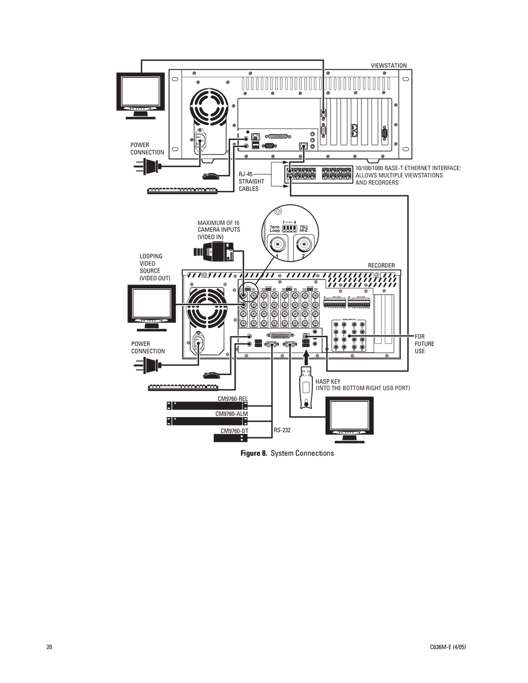
In terms of connectivity, the DX9100 is equipped with various input and output options, such as alarm inputs, relay outputs, and extensive network support. This compatibility facilitates integration with other security systems, such as access control and intrusion detection, creating a comprehensive security infrastructure.
In summary, the Pelco DX9100 stands out as a powerful and reliable surveillance solution. Its combination of high-definition recording, advanced compression technologies, user-friendly interface, remote access capabilities, and extensive integration options makes it an ideal choice for security professionals seeking an efficient and scalable DVR for their monitoring needs.